
Method for improving precision of right angle cutting experiment of carbon fiber composite material

A technology of right-angle cutting and composite materials, which is applied in the field of cutting and processing of difficult-to-machine materials, can solve the problems of sample damage, aggravated tool wear, and damage under the surface, etc., and achieves the effect of simple device, easy operation, and improved experimental accuracy

Active Publication Date: 2015-12-09
DALIAN UNIV OF TECH
View PDF6 Cites 13 Cited by
  • Summary
  • Abstract
  • Description
  • Claims
  • Application Information

AI Technical Summary

Problems solved by technology

However, most of the experimental samples are made by milling, and the milling process is easy to cause damage under the surface, and its depth usually exceeds the depth of cut in the right-angle cutting experiment.
Therefore, if the experimental sample with initial subsurface damage is used for right-angle cutting experiments, the removal process of the material in a non-destructive state cannot be observed, and the cutting force data that can truly reflect the interaction between the material and the tool cannot be obtained
At the same time, there is often a deviation between the actual depth of cut and the experimental preset value in the experiment. If the actual depth of cut is too large, the sample will be seriously damaged due to excessive cutting force, which will aggravate tool wear.
[0003] At present, some scholars have conducted right-angle cutting experiments on carbon fiber composites to study their cutting mechanism, but have not discussed the accuracy of right-angle cutting experiments. For example, the article "Micro-mechanical modeling of machining of FRP composites – Cutting force analysis" published by G. "2007 No. 67, pages 579 to 593, studied the influence of depth of cut, fiber angle, and tool rake angle on cutting force in right-angle cutting. However, the accuracy of right-angle cutting experiments was not discussed.

Method used


Image

  • Method for improving precision of right angle cutting experiment of carbon fiber composite material

Examples


Embodiment Construction

[0018] The specific implementation of the present invention will be described in detail below in conjunction with the technical scheme and accompanying drawings.

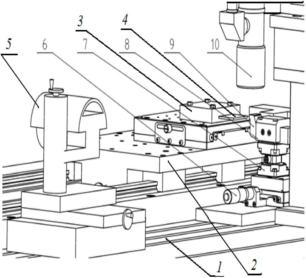
[0019] in the attached figure 1 Among them, a linear motor 2 , a micro-displacement platform 6 and an ultra-depth-of-field microscopic device 10 are installed on the bed 1 . The sample 4 is clamped by the sample holder 3 and installed on the mover of the linear motor 2 . During the experiment, the sample 4 carried by the mover of the linear motor 2 was pretreated by the three-axis grinder 5, the actual depth of cut was measured by the ultra-depth-of-field microscopic device 10, and the actual depth of cut was adjusted by adjusting the micro-displacement platform 6 to make it Same as the experimental preset depth of cut. Then restart the linear motor 2, set its speed as the right-angle cutting speed, and complete the right-angle cutting experiment. The speed adjustment range of the linear motor 2 is 0.1m / s~5m / s, a...


PUM


Abstract

The invention provides a method for improving the precision of a right angle cutting experiment of a carbon fiber composite material, belongs to the field of cutting of hardworking materials and relates to the method for improving the precision of the right angle cutting experiment of the carbon fiber composite material. According to the method, a carbon fiber composite material sample is fixed to a rotor of a linear motor, the rotor carries the sample to preprocess the sample through a three-axis grinder, a damaged area below the initial area of the sample is removed, and the surface, to be machined, of the sample has high flatness; an ultra-field-depth microscopic device is used for accurate tool setting, the practical cutting depth is accurately measured and adjusted so that it can be ensured that the practical cutting depth is equal to the preset value of the experiment, and the precision of the right-angle cutting experiment is improved. According to the method, due to building of an experiment device and experiment setting, the grinder is used for preprocessing, and the experiment is completed through the steps of microscopic tool setting, right angle cutting experiment conducting and the like. The device related to the method is simple, easy to operate and capable of effectively improving the experiment precision of the right angle cutting experiment of the carbon fiber composite material.

Description

technical field [0001] The invention belongs to the field of cutting processing of difficult-to-machine materials, and relates to a method for improving the experimental accuracy of right-angle cutting of carbon fiber composite materials. Background technique [0002] Carbon fiber-reinforced resin-based composite materials present a mixed form of fiber and resin on the microscopic scale, and anisotropy and lamination characteristics on the macroscopic scale, which are prone to damage and tool wear during processing, which restricts the high quality and high efficiency of composite parts. processing. Therefore, it is necessary to reveal the correlation mechanism between the mesoscopic destruction and macroscopic material removal of anisotropic multiphase materials through principle experiments. The principle experiment usually cuts the carbon fiber composite material at right angles, observes the process of the cutting layer material forming chips and detaches from the surfa...

Claims


Application Information

Patent Timeline
Patent Type & Authority Applications(China)
IPC IPC(8): G01N3/58
Inventor 王福吉张博宇宿友亮贾振元陈晨
Owner DALIAN UNIV OF TECH
Learn More