Wearable omnidirectional/directional pattern reconfigurable antenna

A technology for reconstructing antennas and directional diagrams, which is applied to antennas, antenna arrays, and structural forms of radiating elements, can solve problems such as inability to apply wearable antennas and complex structures, and achieve simple structural design, strong practicability, and easy sharing with the human body. shape effect

Active Publication Date: 2015-12-09
HARBIN INST OF TECH
View PDF4 Cites 4 Cited by
  • Summary
  • Abstract
  • Description
  • Claims
  • Application Information

AI Technical Summary

Problems solved by technology

CN1937319A proposes a reconfigurable antenna with omnidirectional/directional pat...

Method used


Image

  • Wearable omnidirectional/directional pattern reconfigurable antenna
  • Wearable omnidirectional/directional pattern reconfigurable antenna
  • Wearable omnidirectional/directional pattern reconfigurable antenna

Examples


specific Embodiment approach 1

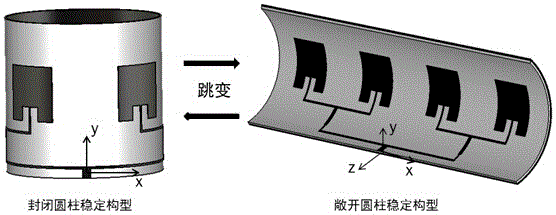
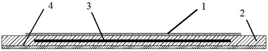
[0030] Specific implementation mode one: as Figure 1-Figure 4 As shown, the wearable omnidirectional / directional pattern reconfigurable antenna provided by this embodiment is composed of an antenna array and its feeding network layer 1, a bistable composite material substrate 2, a jump driver 3 and a ground plate 4, wherein : The antenna array and its feed network 1 are located on the upper layer of the bistable composite material substrate 2, the jump driver 3 is embedded in the middle layer of the bistable composite material substrate 2, and the ground plane 4 is located on the bistable composite material substrate 2 At the bottom layer, all components are integrated with the bistable composite material substrate and solidified.

[0031] In this embodiment, the antenna array and the antenna unit in the feed network layer 1 are microstrip patch units, and the unit size and unit spacing are determined by the operating frequency, the material and the size of the bistable compo...

specific Embodiment approach 2

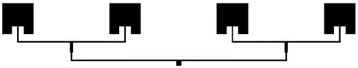
[0036] Specific implementation mode two: as image 3 As shown, the difference between this embodiment and the first embodiment is that the feed mode adopts a parallel feed network. The space required for parallel feeding is large, but its design is simple, and each antenna unit can be fed in the same amplitude and in the same direction. The bistable composite material prepreg is glass fiber prepreg, its single layer thickness is 0.2mm, adopts [0 / 90] layering method, its dielectric constant is 4.9, and dielectric loss is 0.019. Its size is 103mm x 32mm. The antenna is a 1×4 array, and the working frequency is 5.0GHz.

[0037] The antenna array is composed of four identical rectangular patch units with a pitch of 25.75mm, which are just equidistantly laid on the dielectric substrate. The feed network adopts a parallel feed network divided into quarters, and the phases of each unit are the same.

[0038] The jump actuator uses piezoelectric fiber composite (MFC) arrays that d...

specific Embodiment approach 3

[0042] Specific implementation mode three: as Figure 4 As shown, the difference between this embodiment and the second embodiment is that the feeding method adopts a series feeding network, which can reduce the size of the entire reconfigurable antenna. In wearable applications with limited size requirements Suitable for use with feed networks such as wearable belt antennas etc.


PUM

PropertyMeasurementUnit
Beam widthaaaaaaaaaa
Out of roundnessaaaaaaaaaa

Abstract

The invention discloses a wearable omnidirectional/directional pattern reconfigurable antenna. The antenna is formed by an antenna array and a feed network layer thereof, a bistable composite material substrate, a jumping drive, and a grounding plate, wherein the antenna array and the feed network thereof are positioned at the upper layer of the bistable composite material substrate, the jumping drive is embedded into the intermediate layer of the bistable composite material substrate, and the grounding plate is positioned at the bottom layer of the bistable composite material substrate. According to the antenna, antenna pattern omnidirectional/directional reconfiguration is realized by employing two stable configurations of the bistable composite material substrate, and the conversion of the two stable configurations can be realized via the jumping drive; and compared with the conventional wearable antenna, the structure and the design are simple, the antenna and the human body can easily have the same shape, the pattern is reconfigurable, and the antenna is multifunctional and can be applied to the fields of personal wearable mobile communication and field severe environment communication.

Description

technical field [0001] The invention belongs to the technical field of antennas, and relates to a wearable omnidirectional / directional reconfigurable antenna. Background technique [0002] The wearable antenna is an antenna with the human body as the carrier, and it has been widely used in medicine, personal mobile communication, and individual combat communication systems. In order to make the wearable antenna work normally without being affected by the posture and motion of the human body, the wearable antenna is required to radiate omnidirectionally in the horizontal plane, which is beneficial for the antenna to receive signals. However, in some special environments or special tasks, it is required that the wearable antenna can be disassembled and achieve directional radiation, which can improve the antenna radiation performance and shield the direction that does not need to receive signals. Pattern reconfigurable antenna is a potential technical way to realize this requ...

Claims


Application Information

Patent Timeline
IPC IPC(8): H01Q1/38H01Q3/01H01Q21/00
Inventor 戴福洪胡建强李岩奇潘殿坤
Owner HARBIN INST OF TECH
Why Eureka
Try Eureka