Magnetic field modulation type coaxial magnetic gear
A magnetic field modulation and magnetic gear technology, applied in electrical components, electromechanical devices, electromechanical transmission devices, etc., can solve the problems of inability to improve the mechanical strength of the high-speed inner rotor, increase the difficulty of processing and manufacturing the stator, etc., to save consumption, not easily fall off, reduce The effect of manufacturing cost
- Summary
- Abstract
- Description
- Claims
- Application Information
AI Technical Summary
Problems solved by technology
Method used
Image
Examples
Embodiment 1
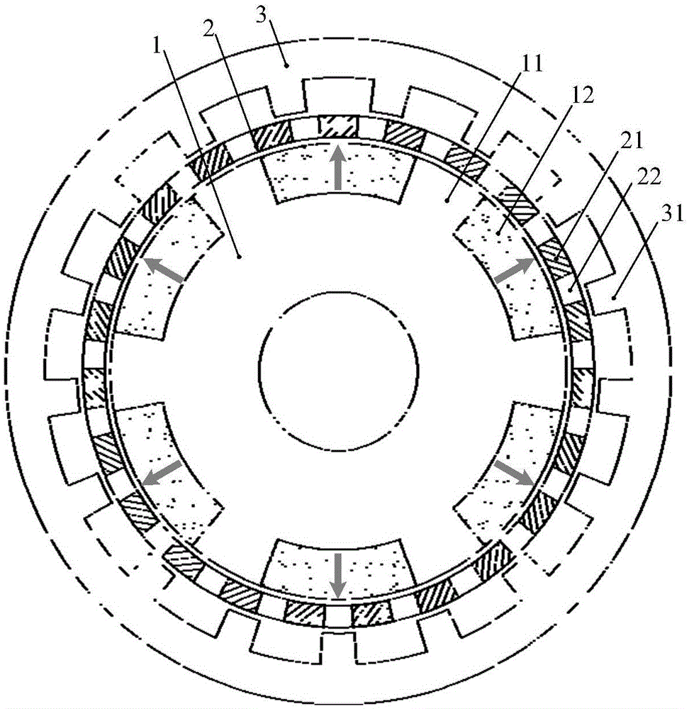
[0032] Such as figure 1 As shown, the magnetic field modulation type coaxial magnetic gear of this embodiment includes: an inner rotor 1, a stator magnetic modulation ring 2 and an outer rotor 3, which are arranged from the inside to the outside and are concentric, this embodiment and the following three embodiments All adopt radial magnetic field type magnetic gears, the stator magnetic modulation ring 2 is located in the air gap between the inner rotor 1 and the outer rotor 3, and there are air gaps between the inner and outer rotors and the stator magnetic modulation ring 2 respectively.
[0033] In this embodiment, the inner rotor 1 is a permanent magnet rotor, and the inner rotor 1 is composed of an inner rotor iron core 11 and an inner rotor permanent magnet 12. The inner rotor permanent magnet 12 is embedded in the permanent magnet installed on the outer surface of the inner rotor iron core 11. In the slot; the outer rotor 3 is a salient pole rotor with uniformly distribute...
Embodiment 2
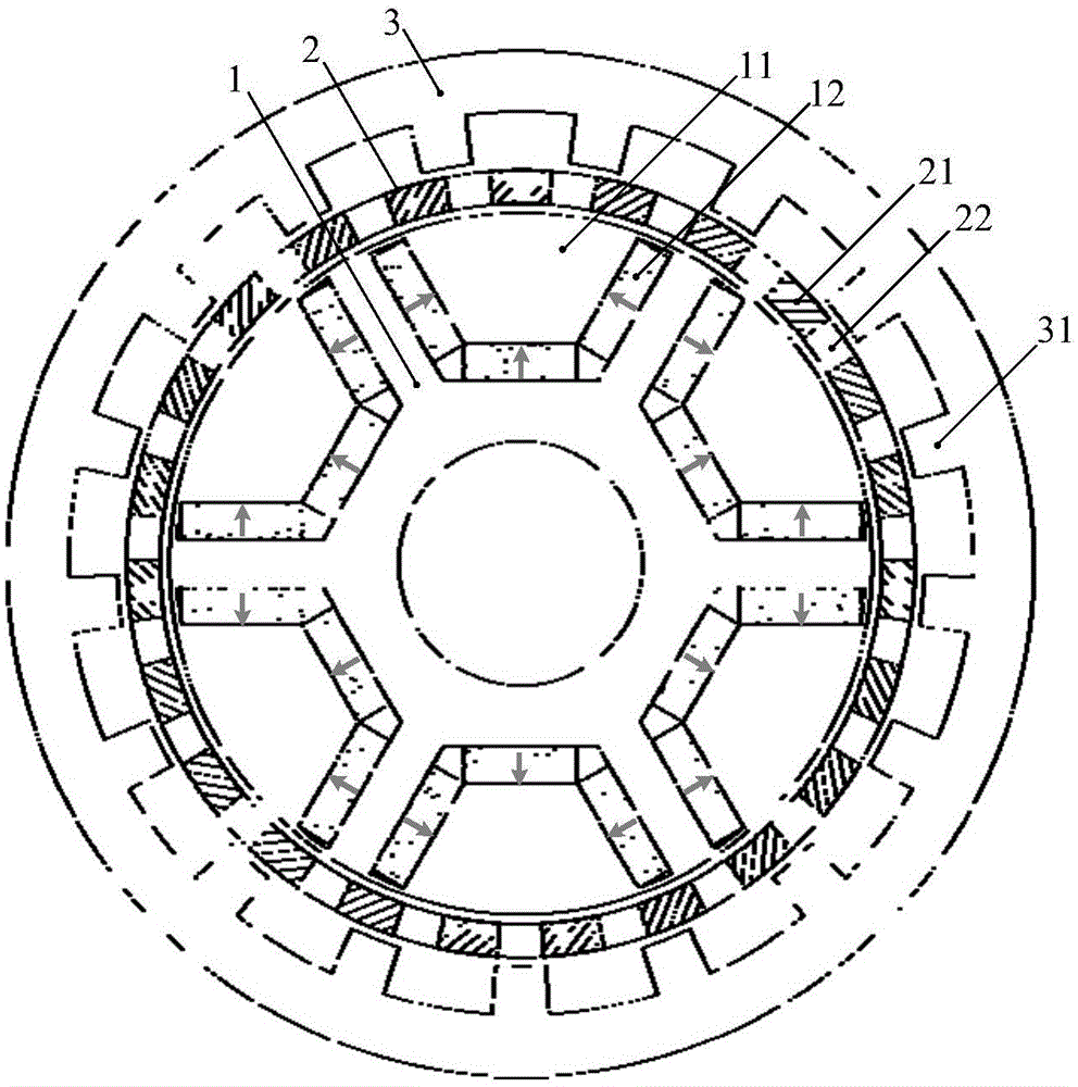
[0041] Such as figure 2 As shown, in this embodiment, except that the structure of the inner rotor 1 is different from that of the embodiment 1, the rest of the structure is the same.
[0042] The permanent magnet installation slot of the inner rotor 1 of this embodiment adopts a built-in type, and the permanent magnets 12 are embedded in the evenly distributed built-in slots of the inner rotor core. The built-in slots are U-shaped slots, and the magnetic direction of each permanent magnet is shown by the arrow , In the U-shaped groove with the same relative position, the relative magnetization direction of each permanent magnet is toward the center of the U-shaped groove, and forms a pair of NS magnetic field loops with the adjacent inner rotor core, and the permanent magnets under a pair of poles provide The magnetic flux is added in parallel, and the built-in slot structure can also adopt other magnetic circuit structures such as radial, tangential, and hybrid. It only needs t...
Embodiment 3
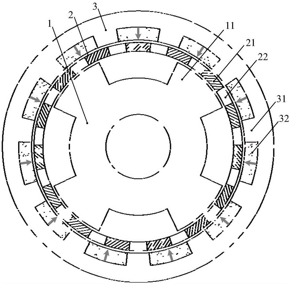
[0044] Such as image 3 As shown, in the magnetic field modulation type coaxial magnetic gear of this embodiment, the inner rotor 1 is a salient pole rotor, with uniformly distributed ferromagnetic salient poles 11 arranged on its outer surface, and the outer rotor 3 is a permanent magnet rotor. The core 31 and the outer rotor permanent magnet 32 are composed. The outer rotor permanent magnet 32 is embedded in the permanent magnet installation slot on the inner surface of the outer rotor core. The permanent magnet installation slot adopts an external slot; the stator magnetic modulation ring 2 is fixedly installed inside and outside Between the rotors, a number of magnetic conductive blocks 21 are evenly distributed along the circumferential direction, and there are air gaps or other non-magnetic materials 22 between adjacent magnetic conductive blocks.
[0045] The magnetic gear outer rotor permanent magnets 32 of this embodiment are embedded in the permanent magnet installat...
PUM
 Abstract
Description
Claims
Application Information
 - R&D
- Intellectual Property
- Life Sciences
- Materials
- Tech Scout
- Unparalleled Data Quality
- Higher Quality Content
- 60% Fewer Hallucinations
Browse by: Latest US Patents, China's latest patents, Technical Efficacy Thesaurus, Application Domain, Technology Topic, Popular Technical Reports.
© 2025 PatSnap. All rights reserved.Legal|Privacy policy|Modern Slavery Act Transparency Statement|Sitemap|About US| Contact US: help@patsnap.com


