Cryogenic treatment device

A technology of cryogenic treatment and placement, which is applied to household refrigeration devices, quenching devices, heat treatment equipment, etc., can solve the problems of uneven cooling of the object to be cooled 101, unstable temperature of the cooling tank 102, and unstable quality of the object to be cooled 101. , to achieve uniform cooling, suppress temperature deviation, and reduce the effect of liquid refrigerant

Active Publication Date: 2017-03-29
NIPPON SANSO CORP
View PDF10 Cites 0 Cited by
  • Summary
  • Abstract
  • Description
  • Claims
  • Application Information

AI Technical Summary

Problems solved by technology

[0014] However, as in the cryogenic treatment apparatus 100 disclosed in Patent Document 1, if the low-temperature nitrogen gas is discharged to the outside of the cooling tank 102 through the exhaust port 102A penetrating the side wall of the cooling tank 102, temperature fluctuations will occur in the cooling tank 102. Stablize
[0015] In this way, if the temperature is unstable in the cooling tank 102, the cooling of the object to be cooled 101 will be uneven, and the quality of the object to be cooled 101 will be unstable.

Method used


Image

  • Cryogenic treatment device
  • Cryogenic treatment device
  • Cryogenic treatment device

Examples


no. 1 approach

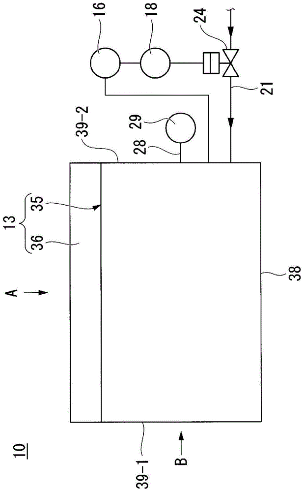
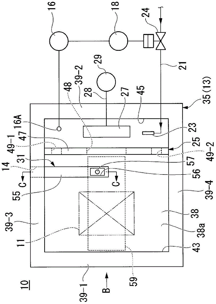
[0043] figure 1 It is a side view showing the appearance of the cryogenic treatment apparatus according to the first embodiment of the present invention. figure 2 is used to describe housed in figure 1 The diagram of the structural elements of the cryogenic treatment device in the main body of the cooling tank is shown through figure 1 The cover body shown is viewed along the A direction figure 1 A top view of the cooling slot shown.

[0044] Thus, in figure 2 In the figure, illustration of the lid body 36 which is a component of the cryogenic treatment apparatus 10 of the first embodiment is omitted.

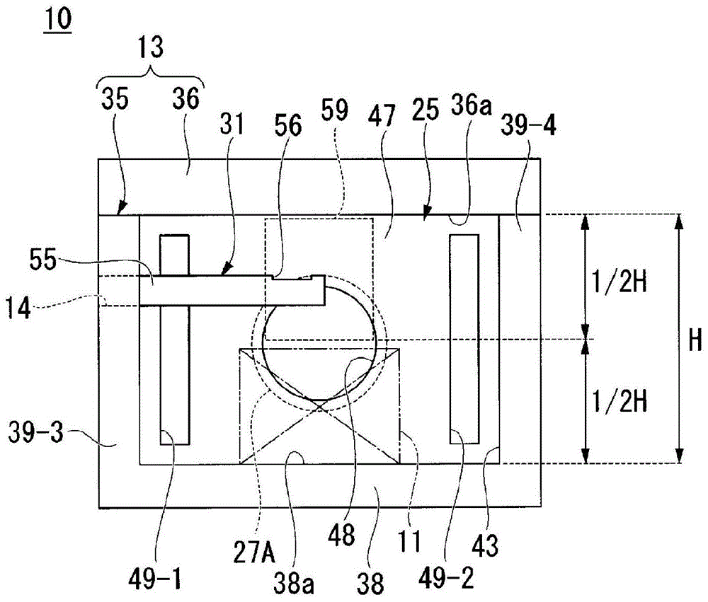
[0045] image 3 is used to describe housed in figure 1 The diagram of the structural elements of the cryogenic treatment device in the main body of the cooling tank is shown through figure 1 The first side wall shown, viewed along direction B figure 1 A diagram of the cooling tank is shown. Thus, in image 3 In the figure, illustration of the first side wall ...

no. 2 approach

[0119] Figure 9It is a figure for explaining the cryogenic processing apparatus which concerns on 2nd Embodiment, and is a figure which looked at the cryogenic processing apparatus from above through the cover which comprises the said cryogenic processing apparatus.

[0120] exist Figure 9 in, right with figure 2 The same structural parts of the cryogenic treatment apparatus 10 of the first embodiment shown are assigned the same reference numerals. In addition, in Figure 9 In the description, for convenience of description, the cover body ( figure 1 An illustration of the cover body 36) shown.

[0121] refer to Figure 9 The cryogenic treatment apparatus 70 of the second embodiment is configured such that instead of the rectifying member 25 constituting the cryogenic treatment apparatus 10 of the first embodiment, and the refrigerated object storage chamber 43 and the fan housing chamber 45 partitioned by the rectifying member 25, it has Except for the rectifying me...


PUM


Abstract

The present invention provides a sub-zero treatment device capable of uniformly cooling a cooling target object and reducing the amount of liquid refrigerant used for cooling the cooling target object. The sub-zero treatment device has an exhaust member extending from a through-hole provided in a cooling tank constituting a cooling target object mounting chamber through to the interior of the cooling target object mounting chamber, and having an exhaust port, wherein the exhaust port is disposed in an exhaust port positioning space, which is the space located in the upper half of the cooling target object mounting chamber and having a width in the transverse direction that is equal to the maximum width in the transverse direction of the suction port.

Description

technical field [0001] The invention relates to a cryogenic treatment device for improving properties such as hardness and toughness by cooling iron and steel materials such as mechanical parts to a low temperature below 0°C. [0002] this application claims priority based on Japanese Patent Application No. 2013-060698 for which it applied to Japan on March 22, 2013, and uses the content here. Background technique [0003] Conventionally, in order to improve performance such as height and toughness of steel materials such as machine parts, cryogenic treatment is performed to cool steel materials such as machine parts to a low temperature below 0°C. [0004] As one of the cryogenic treatment methods, there is known a low-temperature atmosphere method of cooling the object to be cooled by cooling the atmosphere gas in a cooling tank for storing the object to be cooled by a refrigerator or liquid nitrogen. [0005] Patent Document 1 discloses a cryogenic treatment device used ...

Claims


Application Information

Patent Timeline
Patent Type & Authority Patents(China)
IPC IPC(8): F25D3/10C21D1/18
CPCC21D1/62C21D1/613C21D1/64F25D3/10
Inventor 森公哉米仓正浩太田英俊
Owner NIPPON SANSO CORP
Why Eureka
Try Eureka