
Welding method and welding device for thermocouple

A welding method and a welding device technology are applied in the field of thermocouple welding methods and welding devices, which can solve the problems of loss of experimental data production guidance, errors not obtained by scientific researchers, etc., so as to avoid losses, reduce temperature detection errors, and accurately detect temperature. Effect

Active Publication Date: 2015-12-16
CENT SOUTH UNIV
View PDF8 Cites 3 Cited by
  • Summary
  • Abstract
  • Description
  • Claims
  • Application Information

AI Technical Summary

Problems solved by technology

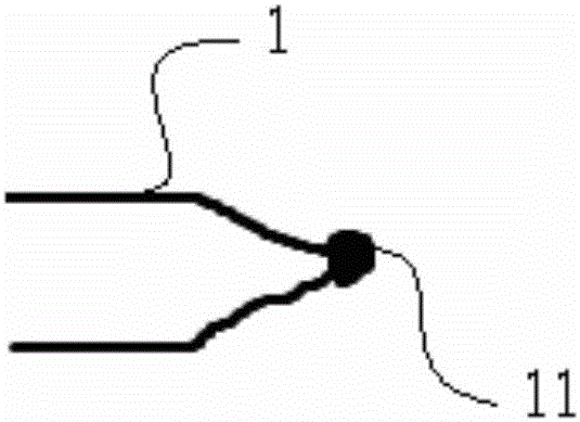
[0003] The thermocouple welded by this traditional method has a larger melting ball in the positive and negative connecting parts, such as figure 2 The tip of the middle thermocouple, the center of the temperature measured in the experiment is the center of the ball, and in the slag crystallization performance experiment, the slag sample is placed at the angle formed by the two thermocouple wires. Therefore, the experiment The measured temperature is not the real temperature of the slag, and the errors caused by this to the experiment have not been paid attention to by scientific researchers for a long time, and the experimental data may bring serious losses to follow-up research or production guidance

Method used


Image

  • Welding method and welding device for thermocouple
  • Welding method and welding device for thermocouple
  • Welding method and welding device for thermocouple

Examples


Embodiment

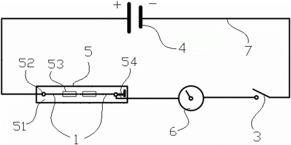
[0028] see image 3 , the thermocouple welding device in the illustration includes a DC power supply 4 , a welding station 5 and a time control unit 6 . Wherein, the welding station 5 includes an insulating base 51. The base 51 of this embodiment is made of a 10mm thick plexiglass plate. The positive and negative poles of the DC power supply 4 are connected by wires to form a DC welding circuit 7, and a time control unit 6 and a switch 3 are arranged in series on the circuit 7, wherein the time control unit 6 uses a time relay to control the welding circuit According to the thickness of the welding thermocouple wire, the on-time of the welding DC circuit is controlled between 0.01ms-1000ms. After the welding time is reached, the time relay automatically disconnects the circuit, and the switch 3 is the welding DC circuit. The main switch of the circuit.

[0029] There are two stoppers 53 between the two terminal posts 52, which are used to limit the welded thermocouple wires ...


PUM


Abstract

The invention discloses a welding method and welding device for a thermocouple. Two straight thermocouple wires are welded in a butt joint mode. The two straight thermocouple wires to be welded are connected in a direct-current circuit. The butted ends of the two thermocouple wires abut against each other in a coaxial mode, and the other ends of the thermocouple wires are connected with the positive pole and the negative pole of a direct-current power source through the circuit respectively. In the welding process, the direct-current circuit is switched on, and meanwhile pressure is applied to the butted ends of the thermocouple wires, the butted ends of the two thermocouple wires are fused and welded together, and the time that the direct-current circuit is switched on is controlled to be 0.01-1000 ms; after welding cooling is conducted, the thermocouple wires welded into a whole are bent at a weld joint. According to the thermocouple welded through the welding method, a welding spot is shrunk remarkably at the weld joint, temperature detection of the thermocouple can be conducted in the test process more accurately, the temperature detection errors caused by welding spot protrusion of the thermocouple are reduced, and the loss caused during the test in industrial production is avoided.

Description

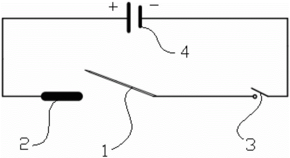
technical field [0001] The invention belongs to the welding process of thermocouples, and in particular relates to a thermocouple welding method and a welding device. Background technique [0002] Thermocouple testing equipment for slag crystallization performance has been widely used in metallurgical industry experimental research. The key unit of the equipment is the thermocouple. The thermocouple is used as the heating element and temperature measuring element of the equipment. influences. The commonly used thermocouple welding method is very simple. The welding circuit is as follows: figure 1 As shown, tightly bind the positive and negative thermocouple wires, then connect one end to the negative pole of a DC power supply of about 30V, and quickly touch the other end to the graphite electrode connected to the positive pole of the power supply to short circuit the circuit The instantaneous huge arc heat released will melt the tip of the thermocouple, so that the positiv...

Claims


Application Information

Patent Timeline
Patent Type & Authority Applications(China)
IPC IPC(8): B23K11/02B23K11/36
CPCB23K11/002B23K11/02B23K11/36
Inventor 王万林马范军罗薛超黄道远周乐君
Owner CENT SOUTH UNIV
Learn More