
Angle-adjustable fan-shaped lead viscoelastic corner damper

A viscoelastic and adjustable technology, applied in building components, shockproof and other directions, can solve the problems of high cost, small yield displacement, inability to meet installation, etc., and achieve the effect of convenient angle adjustment, wide adjustment range and simple structure.

Active Publication Date: 2015-12-16
QINGDAO TECHNOLOGICAL UNIVERSITY +1
View PDF6 Cites 14 Cited by
  • Summary
  • Abstract
  • Description
  • Claims
  • Application Information

AI Technical Summary

Problems solved by technology

[0004] The existing fan-shaped lead viscoelastic corner damper components (such as the authorized announcement numbers are CN101736828B and CN101713226B) have fully utilized the energy dissipation effect of the viscoelastic damper under the action of small deformation and the yield displacement of the lead shear and extrusion type damper The advantages of small size and large limit restoring force make it perform well when applied to earthquake response control and wind vibration response control, but it is limited to use at beam-column joints at 90° angles, and the building structure forms are diverse in socialist modernization construction Under the background of globalization and complexity, a single 90° fan-shaped corner damper cannot meet the installation at large-angle beam-column joints or steel structure joints, and the production of multi-angle corner dampers has higher requirements for production technology and costs also more expensive
There is no corresponding fan-shaped corner damper that can be adjusted at home and abroad

Method used


Image

  • Angle-adjustable fan-shaped lead viscoelastic corner damper
  • Angle-adjustable fan-shaped lead viscoelastic corner damper
  • Angle-adjustable fan-shaped lead viscoelastic corner damper

Examples


Embodiment 1

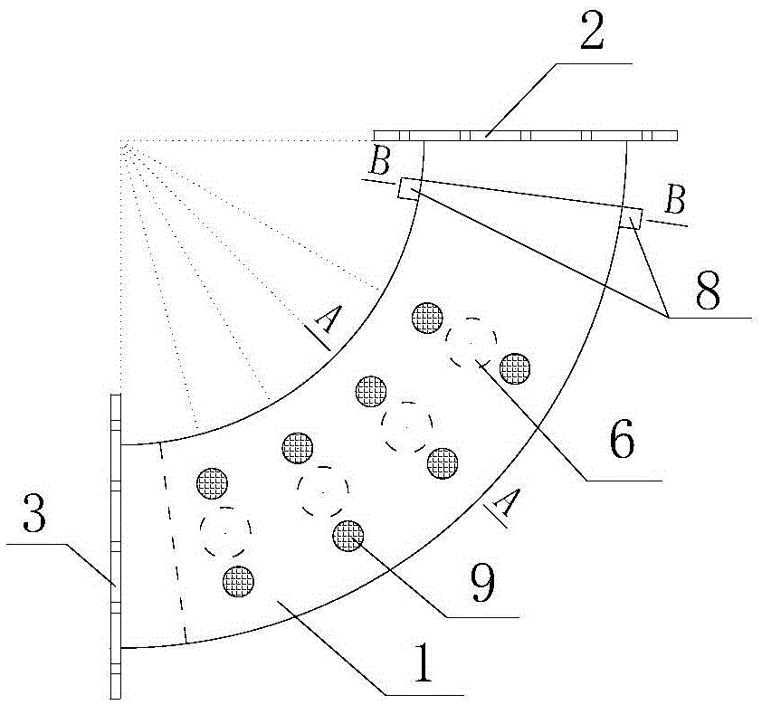
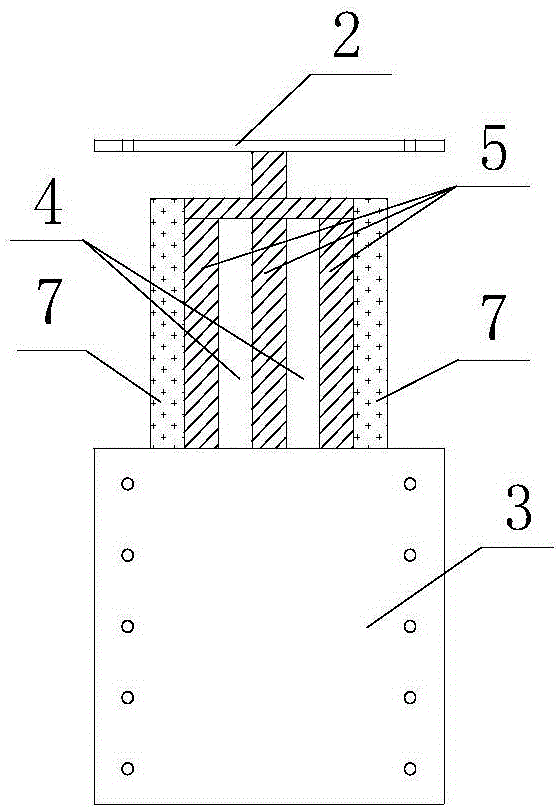
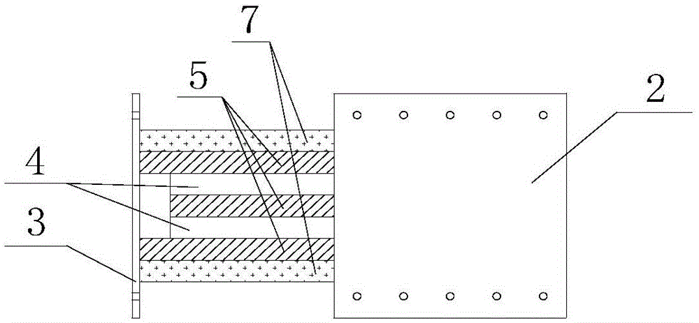
[0028] Such as Figure 1-4 As shown, the composite elastic body 1 is composed of two elastic bodies 4, three shear steel plates 5, four columnar lead cores 6 and two angle adjustment steel plates 7, and the angle adjustment steel plates 7 and the shear steel plates 5 are connected by bolts 9 For connection, the middle shear steel plate 5 is extended and welded to the first connecting plate 2, and the two angle-adjusting steel plates 7 are extended to the other end and welded and fixed to the second connecting plate 3.

[0029] Four columnar lead cores 6 respectively traverse two elastic bodies 4 and three shear steel plates 5 and are distributed along the arc length direction of composite elastic body 1; the center of circle of bolt 9 and the circle center of columnar lead core 6 are located on the same radius, equidistant Distributed on both sides of the columnar lead core 6, there are four groups of bolts 9, eight on each side and sixteen in total. The center angle between ...

Embodiment 2

[0038] Such as Figure 10 As shown, the composite elastic body 1 is composed of four elastic bodies 4, five shear steel plates 5, four columnar lead cores 6 and two angle adjustment steel plates 7, and the angle adjustment steel plates 7 and the shear steel plates 5 are connected by bolts 9 For connection, the three middle shear steel plates 5 are extended and fixed by welding with the first connecting plate 2 , and the two angle-adjusting steel plates 7 are extended to the other end and welded and fixed with the second connecting plate 3 .

[0039] The middle three shear steel plates 5 and the four elastic bodies 4 are pierced with through holes, the outer two shear steel plates 5 are pierced with blind holes, and the columnar lead core 6 passes through the through holes and passes through the blind holes on the outer shear steel plates 5 embedded solid.

[0040] Others are the same as embodiment one.

Embodiment 3

[0042] Such as Figure 11 As shown, the composite elastic body 1 is composed of two elastic bodies 4, three shear steel plates 5, two columnar lead cores 6 and two angle adjustment steel plates 7, and the angle adjustment steel plates 7 and the shear steel plates 5 are connected by bolts 9 The middle shearing steel plate 5 is extended and welded to the first connecting plate 2, and the two angle-adjusting steel plates 7 are extended to the other end and welded and fixed to the second connecting plate 3.

[0043] Two columnar lead cores 6 respectively traverse two elastic bodies 4 and three shear steel plates 5 and are distributed along the arc length direction of the composite elastic body 1; bolts 9 are equidistantly distributed on both sides of the columnar lead core 6 along the arc length direction, and the bolts 9 There are four groups in total, with eight on each side and sixteen in total. The center angle between the centers of adjacent bolts 9 on the same arc length is...


PUM


Abstract

The invention relates to a building component used for node angle displacement limitation and shock absorption, in particular to an angle-adjustable fan-shaped lead viscoelastic corner damper, and belongs to the field of structure engineering. The angle-adjustable fan-shaped lead viscoelastic corner damper mainly solves the problem that the existing fan-shaped lead viscoelastic corner damper component is only limited to be used at a 90-degree angle beam post node position and is difficult to adapt to the modern building structure form diversification. The angle-adjustable fan-shaped lead viscoelastic corner damper comprises a composite elastic body and two connecting plates, wherein the composite elastic body consists of elastic bodies, shearing steel plates, a cylindrical lead core and angle regulating steel plates; the elastic bodies and the shearing steel plates are alternately laminated; the cylindrical lead core transversely passes through the shearing steel plates and the elastic bodies; the shearing steel plates arranged at the outer side are connected with the angle regulating steel plates through screw bolts; and each elastic body, each shearing steel plate and each angle regulating steel plate are all in a fan shape concentric with the composite elastic body. The angle of the damper can be regulated into four different values, and the angle-adjustable fan-shaped lead viscoelastic corner damper is applicable to building structures with various angles.

Description

technical field [0001] The invention relates to a building component for limiting angular displacement of nodes and shock absorption, in particular to an angle-adjustable fan-shaped lead viscoelastic corner damper, which belongs to the field of structural engineering. Background technique [0002] The traditional anti-seismic structure relies on the resistance of the structure itself. By increasing the cross-section of the column and increasing the reinforcement of the beam-column joints to improve the seismic performance of the structural columns and beam-column joints, this not only causes more material consumption, but also makes the Building self-weight increases, and the loss outweighs the gain. The existing lead viscoelastic damper, which can be used for strengthening beam-column joints, is a composite damper, which uses the plastic deformation of lead after shearing or extrusion yielding and the shear hysteretic deformation of viscoelastic materials to consume can. ...

Claims


Application Information

Patent Timeline
IPC IPC(8): E04B1/98
Inventor 张纪刚韩永力李翠翠刘菲菲付为陶雪郑永征
Owner QINGDAO TECHNOLOGICAL UNIVERSITY
Learn More