Shield tunnel heading machine

A technology of shield tunneling and roadheading machine, which is applied in tunnels, mining equipment, earthwork drilling and mining, etc. It can solve problems such as difficult operation, increased labor intensity, and easy wear of cutterhead and edge cutters.

Active Publication Date: 2015-12-16
RAILWAY CONSTR HEAVY IND XINJIANG CO LTD +1
View PDF6 Cites 2 Cited by
  • Summary
  • Abstract
  • Description
  • Claims
  • Application Information

AI Technical Summary

Problems solved by technology

Especially in the stratum with high rock strength, it is very difficult to manually remove the tool replacement space in a narrow space, and the operating environment is very harsh
[0004] During the construction of long-distance and high-strength rock tunnels, the shield tunnel boring machine has complex construction environments, unpredictable working conditions, and high requirements for ground settlement control. Due to the high rock strength and rapid tool wear, Shield tunnel boring machine tunnel excavation diameter changes greatly, and the cutter head wears quickly, especially the edge cutter of the cutter head is easy to wear and needs to be replaced frequently
Under the conditions of large buried depth, high pressure and narrow space, the tool change of the cutter head under pressure increases the difficulty of tool change, increases the labor intensity, and reduces the efficiency of tool change

Method used


Image

  • Shield tunnel heading machine
  • Shield tunnel heading machine
  • Shield tunnel heading machine

Examples


Embodiment Construction

[0033] The present invention will be further described below in conjunction with accompanying drawing.

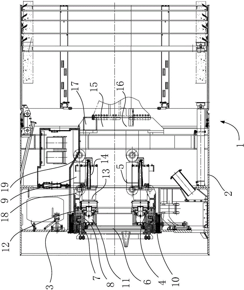
[0034] figure 1 A schematic structural view of a shield tunnel boring machine in an embodiment of the present invention is shown.

[0035] In this embodiment, the shield tunnel boring machine 1 includes a shield shell 2 , a cutter head (not shown), a first driving mechanism 12 , and a second driving mechanism 5 . The cutterhead is arranged outside the shield shell 2 . Both the cutter head and the first driving mechanism 12 are arranged at the front end of the shield shell 2 . The first driving mechanism 12 extends out of the rotating shaft 7, and the rotating shaft 7 is connected to the cutter head. The first driving mechanism 12 is used to drive the cutter head to rotate. The first driving mechanism 12 forms a rotational connection with the shield shell 2 . Preferably, the first driving mechanism 12 forms a ball joint with the shield shell 2 . The second driving mech...


PUM


Abstract

The invention provides a shield tunnel heading machine. The shield tunnel heading machine comprises a cylindrical shield shell, a cutter head, a first driving mechanism and a second driving mechanism; the cutter head is arranged at the front end of the shield shell; the first driving mechanism is rotatably connected with the shield shell; the second driving mechanism is connected with the first driving mechanism; the first driving mechanism comprises a rotating shaft; one end of the rotating shaft is connected with the cutter head; the first driving mechanism is used for driving the cutter head to rotate; and the second driving mechanism is used for driving the first driving mechanism to swing so as to drive the cutter head to swing. After the cutter head swings, pressure of space between cutters at the edge of the cutter head and a stope face of a tunnel can be relieved, a technicist changes the cutters conveniently, labor intensity is reduced, and cutter changing efficiency is improved. In addition, when the edge of the cutter head is jammed by hard substances (such as rock), the cutter head can be released from the hard substances by swinging, and releasing capability of the shield tunnel heading machine is further improved.

Description

technical field [0001] The invention relates to a tunnel boring construction machine, in particular to a shield tunnel boring machine. Background technique [0002] Shield tunnel boring machine is an important construction machine in shield construction. Because shield construction has the advantages of safety, reliability, small environmental impact, low labor intensity, less earthwork, and high efficiency, it is widely used in urban rail, water conservancy, municipal engineering, mines, highways, railway tunnels and other fields. Because the shield tunnel boring machine is often constructed in a complex and long-distance working environment, its transmission system must be able to withstand heavy loads and large impacts, and have functions such as tool change in the hole. [0003] The shield tunnel boring machine mainly works under pressure during the construction process. In the under pressure state, it is required to deal with the problem with the fastest speed and the ...

Claims


Application Information

Patent Timeline
IPC IPC(8): E21D9/08
Inventor 程永亮彭正阳刘华刘派徐震麻成标
Owner RAILWAY CONSTR HEAVY IND XINJIANG CO LTD
Why Eureka
Try Eureka