Gear rack center distance adjusting mechanism

A technology of adjusting mechanism, gear and rack, applied in the direction of belt/chain/gear, mechanical equipment, transmission parts, etc., can solve the problems of inaccurate positioning, long transmission distance, difficult to guarantee the quality of processed workpieces, etc., and achieve accurate positioning accuracy , easy operation and simple structure

Inactive Publication Date: 2015-12-16
JIANGSU YAWEI MACHINE TOOL
View PDF0 Cites 0 Cited by
  • Summary
  • Abstract
  • Description
  • Claims
  • Application Information

AI Technical Summary

Problems solved by technology

[0002] The traditional tool holder is installed on the frame through guide rails, and a set of power transmission device is used to transmit from one side to the other side through the long axis. Due to the long transmission distance, the two ends cannot move synchronously due to various mechanical gaps and errors, resulting in two The ends are not on the same straight line, resulting in errors, resulting in difficult to guarantee the quality of the processed workpiece or even waste products; the traditional drive device is an ordinary motor, due to the heavy mass and large inertia of the tool holder, the positioning accuracy of the tool holder is likely to be inaccurate during the moving process
The existing rack and pinion cooperate to realize the movement of the tool holder. With the long-term use, the center distance between the rack and the gear will gradually increase, resulting in excessive clearance between the rack and pinion, unstable operation and inaccurate positioning.

Method used


Image

  • Gear rack center distance adjusting mechanism

Examples


Embodiment Construction

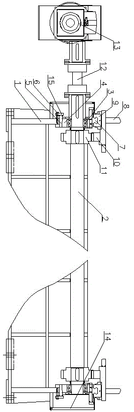
[0014] A rack and pinion center distance adjustment mechanism, including a frame 1 installed on the base, a synchronous shaft 2 is installed on the width direction of the frame 1, and the two ends of the synchronous shaft 2 are installed on both sides of the frame 1 through bearings 3 In the bearing seat, an upper wedge 4 is provided under the bearing seat, and a lower wedge 5 matching with the upper wedge 4 is provided at the lower end of the upper wedge 4, and an adjusting screw 6 is connected to the outer end of the lower wedge 5 , the upper end of both sides of the frame 1 is provided with a linear guide rail 7, and the linear guide rail 7 is provided with a slider 9 installed on the lower end of the knife rest 8, and racks 10 are installed on both sides of the lower end surface of the knife rest 8, and the synchronous rotating shaft 2 There are two synchronous gears 11 on the upper sleeve, and the two synchronous gears 11 are respectively meshed with the rack 10, and one e...


PUM


Abstract

The invention relates to a gear rack center distance adjusting mechanism, which comprises frames which are mounted on a base, wherein a synchronization rotating shaft is mounted in the width direction of the frames; two ends of the synchronization rotating shaft are mounted in bearing seats of two sides of the frames by bearings; upper wedge blocks are arranged under the bearing seats; the lower ends of the upper wedge blocks are provided with lower wedge blocks which are matched with the upper wedge blocks; the outer ends of the lower wedge blocks are connected with adjusting screws; the upper ends of two sides of the frames are provided with linear guide rails; sliding blocks which are mounted on the lower ends of tool rests are arranged on the linear guide rails; racks are mounted at two sides of the lower end faces of the tool rests; two synchronization gears are arranged on the synchronization rotating shaft in a sleeving way; the two synchronization gears are respectively meshed with the racks; and one end of the synchronization rotating shaft is connected with an output shaft of a servo motor by a coupler. The gear rack center distance adjusting mechanism has the advantages that the structure is simple; two ends of the synchronization rotating shaft do synchronous movement, and the movement is stable, so that the positioning precision of the tool rests is high, and the quality of a processed workpiece is ensured.

Description

technical field [0001] The invention relates to a gear rack center distance adjustment mechanism. Background technique [0002] The traditional tool holder is installed on the frame through guide rails, and a set of power transmission device is used to transmit from one side to the other side through the long axis. Due to the long transmission distance, the two ends cannot move synchronously due to various mechanical gaps and errors, resulting in two The ends are not on the same straight line, resulting in errors, resulting in difficulty in guaranteeing the quality of the processed workpiece or even waste products; the traditional drive device is an ordinary motor. Due to the heavy mass and large inertia of the tool holder, the positioning accuracy of the tool holder is likely to be inaccurate during the moving process. The existing rack and pinion cooperate to realize the movement of the tool post. As the time of use is long, the center distance between the rack and the gea...

Claims


Application Information

Patent Timeline
Patent Type & Authority Applications(China)
IPC IPC(8): F16H19/04F16H57/12
CPCF16H19/04F16H57/12
Inventor 潘恩海杨建军朱蔚王刚霍仁洁
Owner JIANGSU YAWEI MACHINE TOOL
Why Eureka
Try Eureka