Eureka AIR delivers breakthrough ideas for toughest innovation challenges, trusted by R&D personnel around the world.
A double crank rocker rack and pinion transmission device
What is Al technical title?
Al technical title is built by PatSnap Al team. It summarizes the technical point description of the patent document.
A rocker, gear and rack transmission technology, applied in the transmission device, transmission element, belt/chain/gear, etc., can solve the problems of unfavorable cylinder and motor life, speed limitation, etc., and achieve the effect of simple structure and low production cost
Active Publication Date: 2017-07-11
ZHEJIANG UNIV
View PDF5 Cites 2 Cited by
Summary
Abstract
Description
Claims
Application Information
AI Technical Summary
This helps you quickly interpret patents by identifying the three key elements:
Problems solved by technology
Method used
Benefits of technology
Problems solved by technology
At present, there is still a solution by repeatedly switching the solenoid valve to drive the cylinder or driving the motor to rotate forward and reverse, but the back and forth movement of the cylinder and the forward and reverse rotation of the motor are not conducive to the life of the cylinder and the motor under high-speed requirements, and there are certain restrictions on the speed.
Method used
Image
Click on the blue label to locate the original text in one second.
Reading with bidirectional positioning of images and text.
Examples
Embodiment Construction
[0014] The present invention will be further described below in conjunction with the accompanying drawings and embodiments.
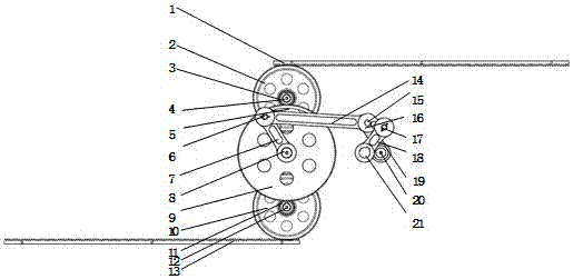
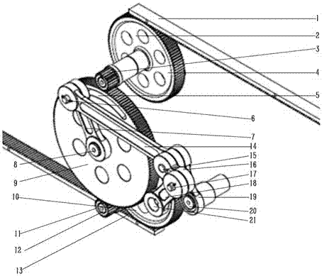
[0015] Such as figure 1 , figure 2 As shown, the present invention includes a first rack 1, a first middle gear 2, a first pinion 3, a first gear shaft 4, an arc groove 5, a rocker pin 6, a rocker 7, a large gear shaft 8, Bull gear 9 , long connecting rod 14 , connecting rod pin 15 , short connecting rod 16 , first crank pin 17 , first crank 18 , second crank 19 , second crankshaft 20 and first crankshaft 21 . The first middle gear 2 and the first pinion 3 are installed on the first gear shaft 4, the first pinion 3 meshes with the big gear 9 mounted on the big gear shaft 8, and the first rack 1 meshes with the first middle gear 2 One end of the rocker 7 is connected with the large gear shaft 8, the rocker pin 6 at the other end of the rocker 7 is slidingly connected with the arc groove 5 on the end face of the large gear 9, and one end of the long co...
PUM
Abstract
The invention discloses a double crank rocker gear rack transmission device which comprises a first rack, a first medium gear, a first small gear, a first gear shaft, arc grooves, a rocker pin shaft, a rocker, a large gear shaft, a large gear, a second medium gear, a second small gear, a second gear shaft, a second rack, a long connecting rod, a connecting rod pin shaft, a short connecting rod, a first crank pin shaft, a first crank, a second crank, a second crank shaft and a first crank shaft. The first crank, the second crank, the short connecting rod, the long connecting rod, the rocker and the three fixed shafts which are the large gear shaft, the second crank shaft and the first crank shaft form a double crank rocker mechanism. The double crank rocker mechanism is combined with a gear rack mechanism, the high-speed reciprocating intermittent linear motion of a motor under unidirectional continuous rotation is achieved, and the intermittent time and displacement can be changed through the rod length of the double crank rocker mechanism and the length of the arc grooves in the gears. The double crank rocker gear rack transmission device is suitable for high-speed reciprocating movement conditions with time remaining and only needs motor driving.
Description
technical field [0001] The invention relates to a mechanical transmission device, in particular to a double crank rocker rack and pinion transmission device. Background technique [0002] Reciprocating backlash motion is traditionally solved by means of mechanism transmission, such as a cam mechanism. At present, there is still a solution by repeatedly switching the solenoid valve to drive the cylinder or driving the motor to rotate forward and backward. However, the back and forth movement of the cylinder and the forward and reverse rotation of the motor are not conducive to the life of the cylinder and the motor under high-speed requirements, and there are certain restrictions on the speed. Contents of the invention [0003] The purpose of the present invention is to provide a transmission device for high-speed reciprocating gap motion, which combines a double crank rocker mechanism and a rack and pinion mechanism to realize high-speed reciprocating gap linear motion und...
Claims
Application Information
Patent Timeline
Application Date:The date an application was filed.
Publication Date:The date a patent or application was officially published.
First Publication Date:The earliest publication date of a patent with the same application number.
Issue Date:Publication date of the patent grant document.
PCT Entry Date:The Entry date of PCT National Phase.
Estimated Expiry Date:The statutory expiry date of a patent right according to the Patent Law, and it is the longest term of protection that the patent right can achieve without the termination of the patent right due to other reasons(Term extension factor has been taken into account ).
Invalid Date:Actual expiry date is based on effective date or publication date of legal transaction data of invalid patent.