
A semi-hydraulic coupler

A technology of hydraulic coupler and shell, applied in the direction of fluid transmission, belt/chain/gear, mechanical equipment, etc., can solve the problems of large working cavity diameter, low mechanical efficiency, narrow speed regulation range, etc., to achieve small size, The effect of light weight and wide speed range

Active Publication Date: 2018-01-12
袁廷华
View PDF6 Cites 0 Cited by
  • Summary
  • Abstract
  • Description
  • Claims
  • Application Information

AI Technical Summary

Problems solved by technology

[0003] The shortcomings of the hydraulic coupling as a speed regulating device are mainly manifested in the narrow speed regulating range and low mechanical efficiency; in addition, the hydraulic coupling uses hydraulic power to transmit power, which makes its working cavity large in diameter and bulky; for high-power hydraulic couplings In addition to the body, there is also a set of auxiliary equipment and pipeline systems such as oil supply pumps, coolers, and oil tanks, which are complicated

Method used


Image

  • A semi-hydraulic coupler
  • A semi-hydraulic coupler
  • A semi-hydraulic coupler

Examples


Embodiment Construction

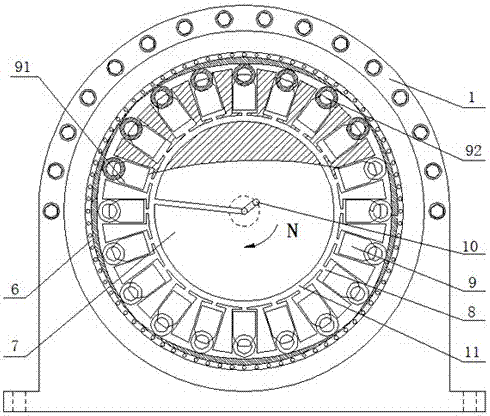
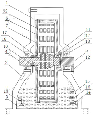
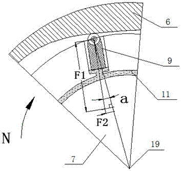
[0028] See figure 1 As shown in Fig. 2, a semi-hydraulic coupling includes a housing 1, a control unit 2 arranged on the outer wall of the housing 1, a high-pressure oil pump 3 arranged in the housing 1 and located at the bottom, and the outer ends of which extend into the outside of the housing 1 The input shaft 4 and output shaft 5, the outer rotor 6 installed in the casing 1 and fixedly connected with the output shaft 5, and the inner rotor 7 sleeved inside the outer rotor 6 and fixedly connected with the input shaft 4; the inner wall of the outer rotor 6 It is a circular variable-diameter curved surface, and the variable-diameter curved surface is evenly divided into multiple equal-divided curved surfaces, each equal-divided curved surface has the same variable-diameter size and direction, and the outer wall of the inner rotor 7 is provided with multiple laps of movable tooth slots 8 , the movable teeth 9 are embedded into the corresponding movable tooth grooves 8 one by ...


PUM


Abstract

The invention discloses a half hydraulic coupler. The half hydraulic coupler comprises an outer shell, an input shaft, an output shaft, an outer rotor and an inner rotor, wherein the outer end of the input shaft and the outer end of the output shaft extend outside the outer shell, the outer rotor is installed in the outer shell and fixedly connected with the output shaft, and the inner rotor is sleeved with the outer rotor and fixedly connected with the input shaft; the inner wall of the outer rotor is a round reducing hook face which is equally divided into a plurality of equally-divided hook face bodies, the reducing size and the direction of the equally-divided hook face bodies are the same, a plurality of movable tooth grooves are formed in the outer wall of the inner rotor, movable teeth are embedded into the corresponding movable tooth grooves in a one-to-one manner, the bottoms of the movable tooth grooves are communicated with a high-pressure oil inlet, and outer ends of the movable teeth face the hook face of the outer rotor. The half hydraulic coupler has the beneficial effects of being wide in speed regulating scope, high in efficiency, small in size and small in weight; the rotating-speed difference is avoided during full-power output power, and meanwhile the soft starting function and outer load impact isolation performance are achieved; as the working efficiency of the half hydraulic coupler is high, the heating amount during working is less, and the half hydraulic coupler has the beneficial effect of being small in number of additional device, high in reliability, low in cost and the like.

Description

technical field [0001] The invention relates to the field of mechanical transmission, in particular to a semi-hydraulic coupler which can amplify the input torque, has high efficiency, and has a large speed ratio variation range in addition to the basic characteristics of the hydraulic coupler. Background technique [0002] The hydraulic coupling currently used has the function of stepless speed regulation, which can realize no-load start-up and overload protection functions, realize the soft connection between the power source and the load, can isolate the impact of load vibration on the power source, and can power the power source when the load fails. It is not damaged, and it is a good solution to the needs of some industrial sites. [0003] The shortcomings of the hydraulic coupling as a speed regulating device are mainly manifested in the narrow speed regulating range and low mechanical efficiency; in addition, the hydraulic coupling uses hydraulic power to transmit pow...

Claims


Application Information

Patent Timeline
Patent Type & Authority Patents(China)
IPC IPC(8): F16H41/00
CPCF16H41/00
Inventor 袁廷华
Owner 袁廷华
Learn More