Pressure adjusting valve

A pressure regulating valve and valve seat technology, which is applied in the field of pressure regulating valves, can solve problems such as large fluctuations in gas pressure fluctuations, potential safety hazards, unstable pressure values ​​of pressure gases, etc., and achieve the effect of stable pressure values

Inactive Publication Date: 2015-12-16
WUHU LION AUTOMOTIVE TECH CO LTD
View PDF6 Cites 1 Cited by
  • Summary
  • Abstract
  • Description
  • Claims
  • Application Information

AI Technical Summary

Problems solved by technology

And because the gas pressure in the pneumatic system is lower than the hydraulic pressure in the hydraulic system, and the gas pressure fluctuation is larger than the hydraulic pressure fluctuation
Therefore, the pressure gas

Method used


Image

  • Pressure adjusting valve

Examples


Embodiment Construction

[0034] In order to make the object, technical solution and advantages of the present invention clearer, the implementation manner of the present invention will be further described in detail below in conjunction with the accompanying drawings.

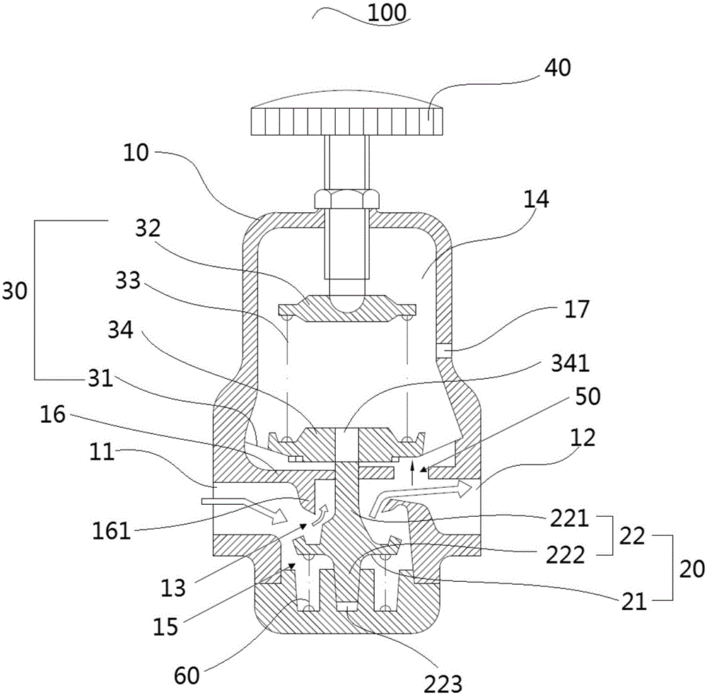
[0035] see figure 1 , which shows a pressure regulating valve 100 according to one embodiment of the present invention. The pressure regulating valve 100 includes a valve body 10 , a valve core assembly 20 , a valve seat assembly 30 , a handle 40 , a damping port 50 , and a return spring 60 . Specifically, the valve body 10 includes a valve cavity and an inlet 11 and an outlet 12 that are arranged on both sides of the valve cavity and communicate with each other. The assembly 30 is provided with a diaphragm 31, and the diaphragm 31 is arranged above the valve core assembly 20; the handle 40 is connected to the upper end of the valve seat assembly 30, and the rotation of the handle 40 makes the valve seat assembly 30 move up and down i...


PUM


Abstract

The invention discloses a pressure adjusting valve belonging to the field of machining equipment and comprising a valve body, wherein the valve body comprises a valve cavity, and an inlet and an outlet which are formed in two sides of the valve cavity and are communicated with each other, and also comprises a valve core assembly, a valve seat assembly, a handle, a damping opening and a reset spring; the valve core assembly is arranged in the valve cavity and can be used for opening and closing the valve opening of the pressure adjusting valve; the valve seat assembly is provided with a diaphragm; the diaphragm is arranged above the valve core assembly; the handle is connected with the upper end of the valve seat assembly; the valve seat assembly can move up and down in the valve cavity by the rotation of the handle; the damping opening is formed in the side of the outlet of the valve cavity; the diaphragm can move up and down in the valve cavity to adjust the size of the damping opening; one end of the reset spring is arranged at the bottom end of the valve core assembly; the other end of the reset spring is fixedly connected with the valve body at the bottom of the valve cavity; during use, output pressure at the outlet is kept, adjusted and determined by balance of force acting on the diaphragm and overflow.

Description

technical field [0001] The invention relates to the field of mechanical processing equipment, in particular to a pressure regulating valve. Background technique [0002] The pneumatic system and the hydraulic system are two different systems. The difference is that for the hydraulic system, each system needs a set of hydraulic energy devices (hydraulic station), but not in the pneumatic system. [0003] Usually, in the pneumatic system, it is necessary to establish an air compressor station uniformly, output compressed air through the air compressor station, and supply the compressed air to multiple sets of pneumatic devices for use. And because the gas pressure in the pneumatic system is lower than the hydraulic pressure in the hydraulic system, and the gas pressure fluctuation is larger than the hydraulic pressure fluctuation. Therefore, the pressurized gas needed to be used in the pneumatic system is often stored in the gas storage tank during use, but at this time the p...

Claims


Application Information

Patent Timeline
IPC IPC(8): F16K3/02F16K3/314F16K27/04F16K31/60
CPCF16K3/0209F16K3/314F16K27/044F16K31/60
Inventor 江涛
Owner WUHU LION AUTOMOTIVE TECH CO LTD
Why Eureka
Try Eureka