
Furnace lining structure of high-temperature vacuum sintering furnace

A high-temperature vacuum and sintering furnace technology, applied in furnaces, muffle furnaces, cooking furnaces, etc., can solve problems such as incompetence for high-temperature sintering and harsh auxiliary facilities

Active Publication Date: 2015-12-16
苏州汇科技术股份有限公司
View PDF11 Cites 2 Cited by
  • Summary
  • Abstract
  • Description
  • Claims
  • Application Information

AI Technical Summary

Problems solved by technology

However, since the sintering temperature of aluminum nitride is relatively high, about 2000 ° C, there are strict requirements for the structure of the furnace body, the heating device and the auxiliary facilities related to the furnace body, that is to say, the conventional high-temperature sintering furnace Not suitable for high temperature sintering of aluminum nitride or similar materials

Method used


Image

  • Furnace lining structure of high-temperature vacuum sintering furnace
  • Furnace lining structure of high-temperature vacuum sintering furnace
  • Furnace lining structure of high-temperature vacuum sintering furnace

Examples


Embodiment Construction

[0025] In order to enable the examiners of the patent office, especially the public, to understand the technical essence and beneficial effects of the present invention more clearly, the applicant will describe in detail the following in the form of examples, but none of the descriptions to the examples is an explanation of the solutions of the present invention. Any equivalent transformation made according to the concept of the present invention which is merely formal but not substantive shall be regarded as the scope of the technical solution of the present invention.

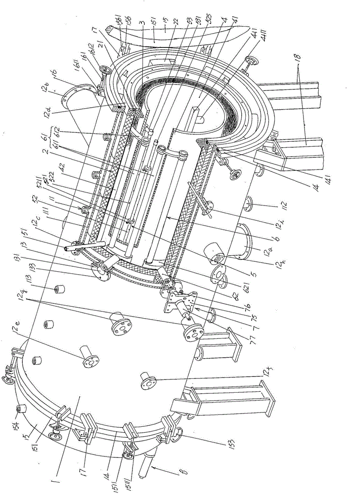
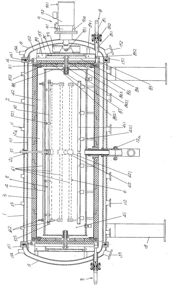
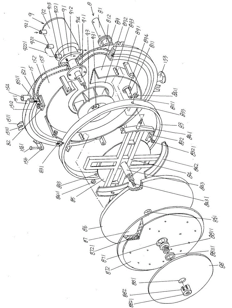
[0026] See figure 1 and figure 2 , a furnace shell 1 belonging to the structural system of a high-temperature vacuum sintering furnace is given. The furnace shell 1 passes through the furnace shell support seat 18 (also called the furnace shell support leg) at the bottom of the furnace shell to vacate the bottom of the floor when it is in use. state and at the same time, it is set on the used floor in a hor...


PUM


Abstract

The invention relates to a furnace lining structure of a high-temperature vacuum sintering furnace, belonging to the technical field of high-temperature sintering furnaces. The high-temperature vacuum sintering furnace comprises a furnace shell, a furnace tube, a protective gas introduction mechanism and a furnace tube heating mechanism, wherein the furnace shell is provided with a furnace shell cooling mechanism; a furnace bed is arranged in the furnace tube cavity; the protective gas introduction mechanism is connected with a protective gas supply source through a pipeline; and the furnace tube heating mechanism is connected with a feed mechanism. The furnace lining structure comprises a furnace cylinder and a furnace cylinder inner sleeve, wherein a furnace cylinder door cover ring is respectively embedded in the left end and right end ports; the furnace cylinder inner sleeve is arranged in the furnace cylinder cavity and contacts the wall of the furnace cylinder cavity; a space is kept between the outer wall of the furnace tube and the furnace cylinder inner sleeve; the furnace cylinder is composed of a set of furnace cylinder sections; the furnace cylinder inner sleeve is a carbon fiber bushing; the furnace tube is prepared from graphitic carbon fibers; the inner wall of each furnace cylinder door cover ring is composed of a conical surface; one side of each furnace cylinder door cover ring is provided with a furnace cylinder embedding cavity; one side of the furnace cylinder door cover against the furnace cylinder is provided with a graphite ring caulking groove; a graphite ring is arranged in each graphite ring caulking groove; and the circumferential surface of the furnace cylinder door cover is matched with the conical surface. The furnace lining structure improves the sintering temperature uniformity of the product in the furnace tube cavity and ensures the sintering quality.

Description

technical field [0001] The invention belongs to the technical field of high-temperature sintering furnaces, and in particular relates to a lining structure of a high-temperature vacuum sintering furnace. Background technique [0002] The high-temperature vacuum sintering furnace mentioned above was born under the background of "the tool must be sharpened first if you want to do it well". Taking the aluminum nitride (ALN) substrate belonging to the category of diamond-like nitride as an example, because it has not Limited to the advantages of the following aspects: high thermal conductivity, about 20W / m·k, close to BeO and SiC, and Al 2 o 3 More than five times; the coefficient of thermal expansion is small, at 4.5×10 -6 ℃, with Si (3.5~4×10 -6 °C) and GaAs (6×10 -6 ℃) are comparable; the electrical properties are excellent, specifically, the dielectric constant, dielectric loss, volume resistivity and dielectric strength are excellent; the mechanical properties are ideal...

Claims


Application Information

Patent Timeline
IPC IPC(8): F27B5/05F27B5/08F27B5/14F27B5/16F27D1/00F27D1/12F27D1/18F27D7/02F27D11/00
Inventor 陈斌张文俊
Owner 苏州汇科技术股份有限公司
Learn More