Laminar flow element

A component, solid technology, applied in the detection of fluid flow by measuring differential pressure, volume/mass flow generated by mechanical effects, etc., can solve the problems of difficult processing, high price, narrow flow range, etc., to achieve stable laminar flow, processing The effect of high precision and wide flow range

Active Publication Date: 2015-12-16
陕西易度智能科技有限公司
View PDF9 Cites 9 Cited by
  • Summary
  • Abstract
  • Description
  • Claims
  • Application Information

AI Technical Summary

Problems solved by technology

[0005] The purpose of the present invention is to provide a laminar flow element, which solves the problems that the existing laminar flow element is too expensive, difficult to process, unstable laminar flow effect, and narrow applicable flow range

Method used


Image

  • Laminar flow element
  • Laminar flow element
  • Laminar flow element

Examples


Embodiment 1

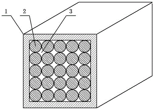
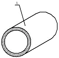
[0017] The wall thickness of the hollow cylinder 1 is 5mm, the length is 30mm, and the size of the square through hole is 10*10mm. The material of the hollow cylinder 1 can be selected from materials such as stainless steel, aluminum alloy or ceramics.

[0018] 100 solid round rods 2 with a smooth surface, a diameter of 1 mm, and a length of 30 mm are closely arranged along the axial direction of the through hole in the hollow cylinder 1 . The arrangement of the solid round rods 2 in the hollow cylinder is arranged in parallel. The hollow cylinder 1 and the solid round rod 2 are fixed with each other through interference fit. The hollow cylinder 1 and the solid round rod 2 , and the gap between the solid round rods 2 form a laminar flow channel 3 . The solid round rod 2 can be made of materials such as stainless steel, aluminum alloy or pottery.

[0019] When the laminar flow element is actually used, the fluid passes through the laminar flow channel 3 to form a laminar flo...

Embodiment 2

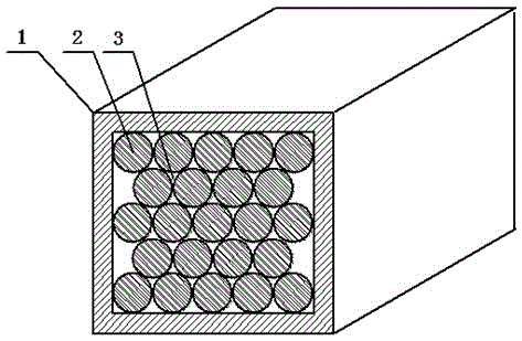
[0022] The discharge method of the solid round rod 2 in the laminar flow element can also adopt another method, such as figure 2 As shown, the solid round rods 2 are closely arranged in the fork row in the hollow cylinder 1, and the specific scheme refers to the first embodiment. Compared with the first embodiment, the laminar flow formed by the laminar flow element in this embodiment is more stable.

Embodiment 3

[0024] The laminar flow element can also be made by using a solid round rod 2 with a diameter of 3 mm. For a specific implementation, please refer to the method of using a solid round rod 2 with a diameter of 1 mm to make a laminar flow element. Compared with the first embodiment, in this embodiment, the laminar flow stability formed by the laminar flow element is lowered, and the applicable flow range is slightly lowered, but the manufacturing cost is lowered.


PUM


Abstract

The invention discloses a laminar flow element. The element is composed of a hollow cylinder body and solid round bars, the solid round bars are closely arrayed inside the hollow cylinder body, the solid round bars are fixed to the hollow cylinder body through interference fit, each solid round bar is fixed to the adjacent solid round bars through interference fit, laminar flow channels are constituted by gaps between the solid round bars and the hollow cylinder body and among the solid round bars, and fluid flows through the laminar flow channels, so that laminar flow is formed. The laminar flow element has the advantages of being low in fabrication cost, high in stability of the formed laminar flow and wide in applicable flow scope.

Description

technical field [0001] The invention relates to the field of flow measurement. Background technique [0002] The laminar flow element is an element that converts the flow state of the fluid into laminar flow, and is mainly used in the field of flow measurement. [0003] At present, the mainstream laminar flow components are generally made of capillary tubes, allowing the fluid to flow through the capillary tubes to form a laminar flow, and then several capillary tubes are bundled to form a laminar flow component; The gap between forms laminar flow. For example, the patent No. CN201220237073.9 discloses a capillary-type laminar flow element, which uses a cylindrical corrosion-resistant polymer material to inlay stainless steel thin tubes to form a laminar flow element. The corrosive polymer material is polytetrafluoroethylene, and the laminar flow element is pressed into the inside of the valve body, and has an interference fit with the valve body. [0004] The production ...

Claims


Application Information

Patent Timeline
Patent Type & Authority Applications(China)
IPC IPC(8): G01F1/34
CPCG01F1/34
Inventor 王文东王筱庐张凯王泽元肖攀唐晓晨边陇峰
Owner 陕西易度智能科技有限公司
Why Eureka
Try Eureka