Method for accurate detection of material defect and thickness by using digital radiography transillumination technology

A digital ray and material detection technology, which is applied in the use of radiation for material analysis, measuring devices, and the use of wave/particle radiation, etc., can solve problems such as large residual height fluctuations, differences in final gray levels, and the inability of users to confirm precise positions.

Active Publication Date: 2015-12-16
赵建江
View PDF6 Cites 11 Cited by
  • Summary
  • Abstract
  • Description
  • Claims
  • Application Information

AI Technical Summary

Problems solved by technology

[0024] 2) Measurement error: Generally, the defects that need to measure the depth in the workpiece are thin-line, and the characteristics displayed on the film are thin black lines, such as incomplete penetration, incomplete fusion, undercut, etc., the width of such defects Generally below 0.5MM or even smaller, while the groove width of the groove-type comparison test block is 2MM. For the blackness meter used for measurement, the dotted needle is at the millimeter level. When used to measure the blackness of the groove-type test block groove , can find its position, when measuring the blackness of the defect, it is often difficult to find its position, one is that the width of the defect is much smaller than the width of the needle, and the other is that the film is black under natural light, and it is difficult for the human eye to distinguish the exact position of the defect , so the measurement error is large
This situation will cause the user to be unable to confirm the precise location of the comparison during reality detection
[0029] 3. More importantly, there is a possibility of misjudgment (inaccu

Method used


Image

  • Method for accurate detection of material defect and thickness by using digital radiography transillumination technology
  • Method for accurate detection of material defect and thickness by using digital radiography transillumination technology
  • Method for accurate detection of material defect and thickness by using digital radiography transillumination technology

Examples


Embodiment Construction

[0073] Time: July 15, 2015

[0074] Workpiece condition: steel plate + slope test block + gradient step test block

[0075] Test purpose: to verify the use of a fixed slope test block to measure the depth difference between two defects in a gradient test block with a (steel plate) background (simulate the height of the defect inside the weld)

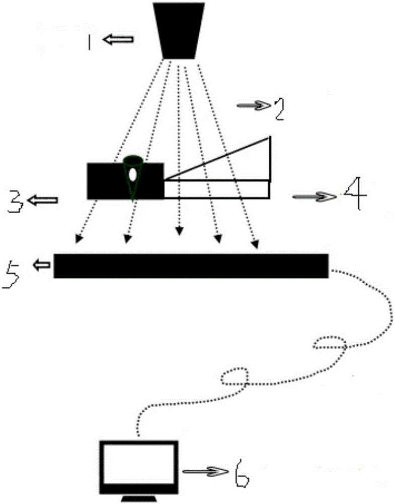
[0076] Introduction of the equipment used:

[0077] Equipment: U.S. Varian 2520 flat panel detector

[0078] Using CP160 radiographic machine from Belgium ICM

[0079] Description of workpiece and test block:

[0080] 1. 7mm thick steel plate as background (simulating the thickness of pipe or flat plate)

[0081] 2. 3.5mm thick test block with 5 step grooves (see the above table H.2II type comparison test block, the depth is 0.5, 1.0, 1.5, 2.0, 2.5), we only use the first defect (depth 0.5mm , The depth difference between the actual remaining thickness of the test block 3mm) and the second defect (depth 1mm, the actual remaining thickness of the te...


PUM


Abstract

The invention provides a method for accurate detection of material defect and thickness by using a technology of digital radiography transillumination, and belongs to the field of nondestructive test. A test block with fixed gradient is placed on a material to be detected, a radiation field from top to bottom passes through a workpiece to be detected and the test block with fixed gradient at the same time, a digital ray reception plate receives attenuated ray, and the ray is converted into a two-dimensional image by a data displaying and processing unit. According to a flat weld detection, the test block with fixed gradient is placed beside the workpiece to be detected; the cross section of the test block is a right trapezoid, wherein a right-angle side is horizontally placed on the horizontal plane same to that of the workpiece; according to a small diameter tube detection, a test block with gradient is used, and the cross section of the test block along the axial direction of the test block is semi-toroidal, and the cross section of the test block along the circumferential direction is right trapezoid; internal diameter of the test block with gradient is equal to the external diameter of the small diameter tube, and the cross section of the test block with gradient is semi-toroidal, the test block is tightly wrapped outside the workpiece to be detected and is placed beside the weld. The method can be used for accurately measuring height of the defect and weld reinforcement or the like without misjudgement.

Description

Technical field [0001] The invention discloses a method for accurately detecting defects and thicknesses of materials by digital radiographic technology, and belongs to the field of nondestructive testing. Background technique [0002] 1. Industrial radiography technology [0003] Radiographic inspection is a kind of non-destructive inspection, including X-ray inspection, γ-ray inspection, high-energy ray inspection and neutron ray inspection. For industrial ray inspection, X-ray inspection and gamma ray inspection are generally used. The principle is: when a beam of uniform intensity irradiates an object, if there is a defect or a difference in structure in the local area of ​​the object, it will change the attenuation of the object to the ray, so that different parts of the transmitted ray have different intensities. In this way, a certain detector is used (For example, film is used in radiography) by detecting the intensity of transmitted rays, it is possible to judge the defe...

Claims


Application Information

Patent Timeline
IPC IPC(8): G01N23/04G01B15/02
Inventor 赵建江
Owner 赵建江
Why Eureka
Try Eureka