Oil-gas separation cylinder, oil-gas separation device and oil chromatography

A separation device and separation cylinder technology, applied in the direction of material separation, measuring device, separation method, etc., can solve the problems of complex structure, poor effect, long time spent, etc., and achieve the effect of simple structure of the device and enhanced degassing effect

Inactive Publication Date: 2015-12-16
XUJI GRP +3
View PDF8 Cites 4 Cited by
  • Summary
  • Abstract
  • Description
  • Claims
  • Application Information

AI Technical Summary

Problems solved by technology

However, it takes a long time to separate the oil and gas by stirring, and the effect is poor, and the structure of the whole oil and gas separation device is complicated and takes up a lot of space due to the use of the stirring motor and the degassing chamber

Method used


Image

  • Oil-gas separation cylinder, oil-gas separation device and oil chromatography
  • Oil-gas separation cylinder, oil-gas separation device and oil chromatography
  • Oil-gas separation cylinder, oil-gas separation device and oil chromatography

Examples


Embodiment Construction

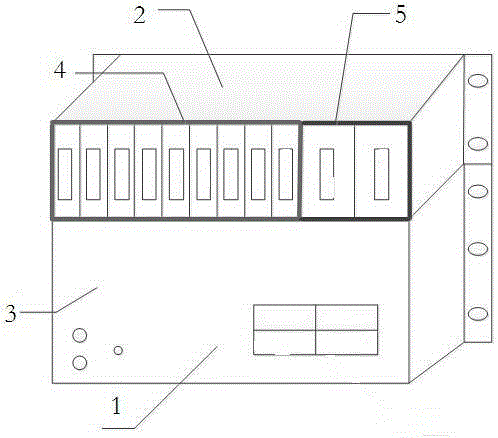
[0019] The structural representation of the embodiment of a kind of oil chromatography is as figure 1 As shown, it includes transformer oil extraction and oil-gas separation layer 1 and transformer fault gas analysis and diagnosis layer 2. Transformer oil extraction and oil-gas separation layer 1 includes oil-gas separation module 3, chromatographic column and semiconductor detector; transformer fault gas analysis and diagnosis layer 2 includes fault analysis module 4 and power supply module 5, fault analysis module 4 includes communication, fault analysis and CPU plug-in for data storage, three outlet plug-ins responsible for controlling each component, expansion plug-in for power outlet expansion, DC plug-in for DC signal acquisition and processing, and DC signal processing and sending the DC signal to the CPU in the form of a bus The collection plugin for plugins. Among them, the fault analysis module 4 is based on the concept of VLD visual programming control to realize t...


PUM


Abstract

The invention relates to an oil-gas separation cylinder, an oil-gas separation device and oil chromatography. The oil-gas separation cylinder comprises a cylinder body and an isolating block, wherein the isolating block separates an inner cavity of the cylinder body into upper and lower chambers, a piston of the oil-gas separation cylinder is assembled in the lower chamber in a guiding movement manner, an oil inlet channel, an oil outlet channel and an oil cylinder gas exhaust port which are communicated with the upper chamber are formed in the oil-gas separation cylinder, and an oil guide hole and a spray hole which are communicated with the upper and lower chambers are formed in the isolating block or an oil guide and spray hole communicated with the upper and lower chambers is formed in the isolating block. The spray effect of transformer oil is realized through vertical movement of the piston of the oil-gas separation cylinder, the oil-gas balance is realized quickly, dynamic dilatation is performed in an effective degassing space, and the degassing effect is enhanced. The vacuum spray manner is adopted, and a stirring motor for continuously stirring the transformer oil in the prior art is omitted, so that the whole device is simple in structure.

Description

technical field [0001] The invention belongs to the field of transformer detection in power systems, and in particular relates to an oil-gas separation cylinder, an oil-gas separation device and an oil chromatography. Background technique [0002] At present, the oil chromatography detection device of the transformer mainly adopts a cabinet-type overall design, that is, all the valve bodies and electrical components used in the transformer oil chromatography device are installed in the entire cabinet according to the structure of the cabinet. This design structure is complex and the anti-interference ability Poor, there are many additional resource configurations, a waste of resources, a large space occupation, and inconvenient maintenance and installation. The utility model patent of Chinese patent document CN201425590Y discloses a vacuum degassing device for online chromatographic analysis of transformer oil, including an oil pump, an oil cylinder, a cylinder, a degassing ...

Claims


Application Information

Patent Timeline
Patent Type & Authority Applications(China)
IPC IPC(8): G01N30/06G01N30/02
CPCB01D19/0036B01D15/12B01D19/0042
Inventor 周水斌庄益诗王伟杰王胜辉和红伟刘畅邵秋华路光辉雍明超卢声王国玉龚东武牧继清梁武民刘建勇
Owner XUJI GRP
Why Eureka
Try Eureka