
Intelligent optical fiber moveable connector

An active connector and intelligent optical fiber technology, applied in the field of optical communication, can solve the problems that optical fiber jumpers do not have information storage and reading functions, it is difficult for fiber jumper manufacturers to manage quality, and fiber jumper maintenance and operation are inconvenient. , to achieve the effect of avoiding resource waste, improving resource utilization and long service life

Inactive Publication Date: 2015-12-16
JIANGSU XINDA COMM TECH
View PDF8 Cites 2 Cited by
  • Summary
  • Abstract
  • Description
  • Claims
  • Application Information

AI Technical Summary

Problems solved by technology

[0002] Traditional optical fiber jumpers (which are composed of optical fibers and connectors) do not have information storage and reading functions, or use paper labels to paste paper labels on both ends of the optical fiber jumper to indicate the number and simple information of the optical jumper , it is difficult for optical fiber jumper manufacturers to realize process-based quality management, product process control, product quality analysis and traceability of their products
At the same time, paper labels are easily affected by the surrounding environment and manual operations, and the labels are easily aged or damaged, which may lead to missing labels or incorrect connections when updating the position of the fiber jumper, which brings great harm to the maintenance and operation of the fiber jumper users. Inconvenient, increased labor costs

Method used


Image

  • Intelligent optical fiber moveable connector
  • Intelligent optical fiber moveable connector
  • Intelligent optical fiber moveable connector

Examples


Embodiment

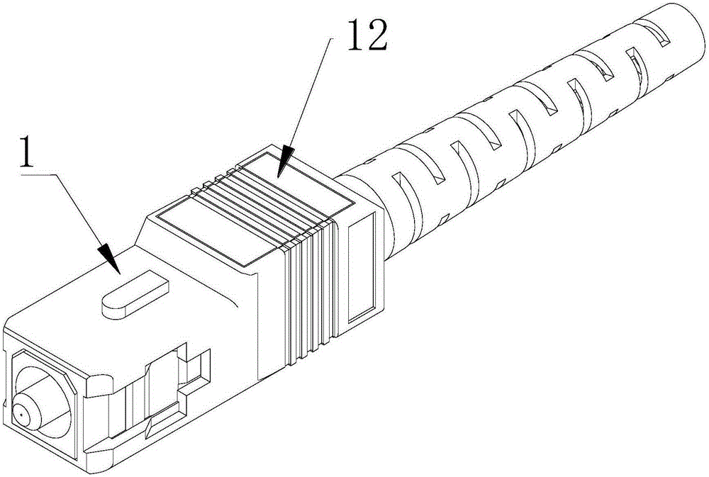
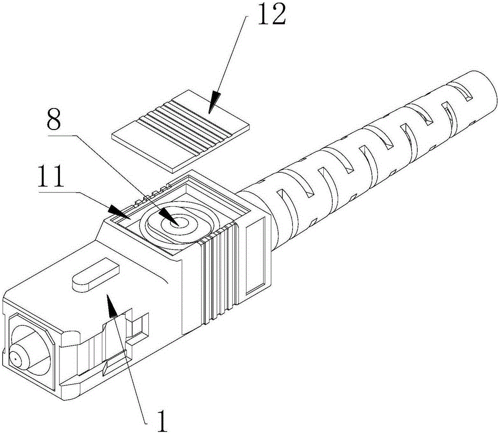
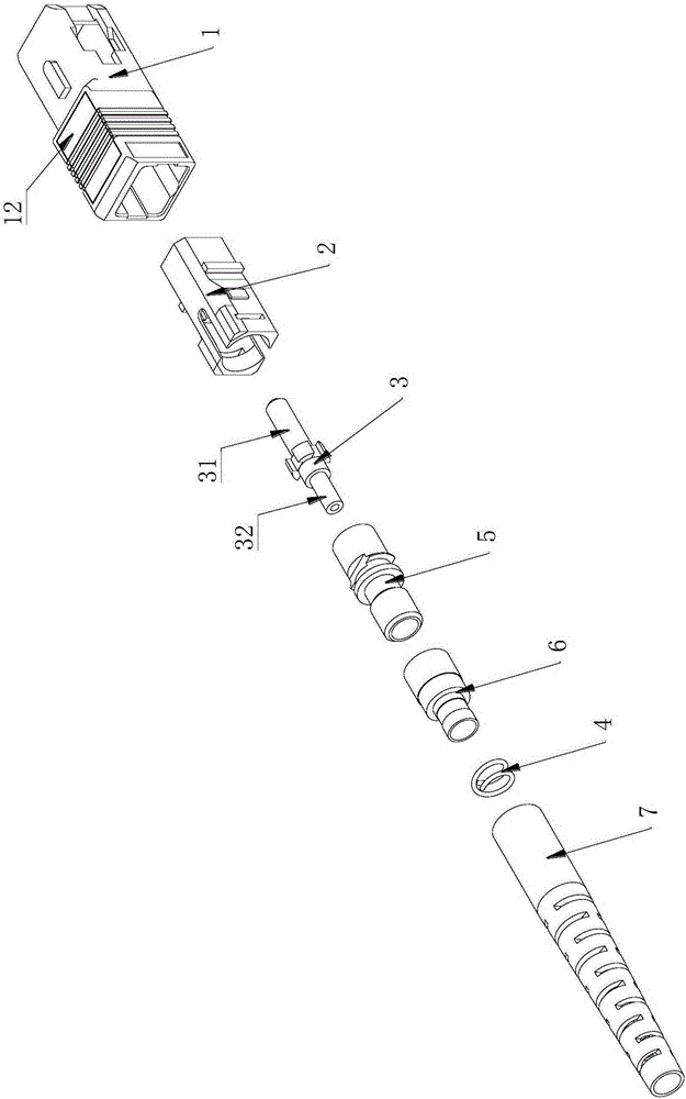
[0017] Example: such as Figure 1 to Figure 4 As shown, an intelligent optical fiber active connector includes an outer frame sleeve 1, an inner bushing 2, a ferrule assembly 3, a spring 4, a stopper tube 5, a clip tube 6 and a tail sleeve 7, and the ferrule assembly 3 is composed of The ceramic ferrule 31 is composed of a ferrule handle 32 connected to the rear end of the ceramic ferrule 31. The spring 4 is sleeved on the ferrule handle 32. Ring-shaped convex edge, the rear end of the spring 4 is against the step 5 of the inner hole of the stop tube 5, the front end of the clamp tube 6 is sleeved on the outer wall of the rear end of the stop tube 5, and the rear end of the inner bushing 2 The end is sleeved on the front end of the stopper tube 5, the front end of the tail sleeve 7 is sleeved outside the pinch tube 6, the outer frame sleeve 1 is sleeved on the front end of the inner bush 2 and the tail sleeve 7, the outer frame The set 1 is provided with an RFID tag 8 .

[0...


PUM


Abstract

The invention discloses an intelligent optical fiber moveable connector. The intelligent optical fiber moveable connector comprises an outer frame sleeve, a liner sleeve, a ferrule assembly, a spring, a blocking tube, a clamping tube and a tail sleeve; the ferrule assembly is composed of a ceramic ferrule and a ferrule tail handle; the spring sleeves the ferrule tail handle; the front end of the spring abuts against a circular protruding edge of the front end portion of the ferrule tail handle; the back end of the spring abuts against the step of the inner cavity wall of the blocking tube; the front end of the clamping tube sleeves the outer wall of the back end portion of the blocking tube; the rear end of the liner sleeve sleeves the front end portion of the blocking tube; the front end of the tail sleeve sleeves the clamping tube; the back end surface of the liner sleeve is connected with the front end surface of the tail sleeve; the outer frame sleeve sleeves the exteriors of the front end portions of the liner sleeve and the tail sleeve; and the outer frame sleeve is provided with a RFID (radio frequency identification) label. According to then intelligent optical fiber moveable connector of the invention, the RFID (radio frequency identification) label is arranged in the connector, and therefore, various kinds of information of the optical fiber patch cord can be recorded into a chip or can be read through a card reader according to the requirements of a user, and quick identification and management of the optical fiber patch cord can be facilitated.

Description

technical field [0001] The invention relates to the field of optical communication, in particular to an optical fiber active connector. Background technique [0002] Traditional optical fiber jumpers (which are composed of optical fibers and connectors) do not have information storage and reading functions, or use paper labels to paste paper labels on both ends of the optical fiber jumper to indicate the number and simple information of the optical jumper Therefore, it is difficult for optical fiber jumper manufacturers to implement process-based quality management, product process control, product quality analysis and traceability for their products. At the same time, paper labels are easily affected by the surrounding environment and manual operations, and the labels are easily aged or damaged, which may lead to missing labels or incorrect connections when updating the position of the fiber jumper, which brings great harm to the maintenance and operation of the fiber jumpe...

Claims


Application Information

Patent Timeline
IPC IPC(8): G02B6/36
CPCG02B6/3624
Inventor 何伟
Owner JIANGSU XINDA COMM TECH
Learn More