A kind of cob light source and its preparation process

A preparation process and technology for light sources, applied in electrical components, circuits, semiconductor devices, etc., can solve the problems of uneven light distribution of light source chips, long time required, inconvenient production, etc., and achieve good color temperature consistency and good consistency. , The effect of stable product quality

Active Publication Date: 2017-08-25
淮安吉山光电科技有限公司
View PDF6 Cites 0 Cited by
  • Summary
  • Abstract
  • Description
  • Claims
  • Application Information

AI Technical Summary

Problems solved by technology

[0002] Most of the conventional phosphor precipitation processes are simply achieved by standing at room temperature or accelerating precipitation in a centrifuge. The phosphor precipitation effect is as follows: figure 1 As shown, only the upper surface of the light source chip and the upper surface of the copper substrate are deposited with phosphor powder, while the side wall of the LED chip has no phosphor powder, resulting in serious uneven light distribution of the light source chip
If it is left standing at room temperature, it will take a long time and the production is inconvenient; if the centrifuge equipment is used, the investment will be large; the effect of both is not ideal

Method used


Image

  • A kind of cob light source and its preparation process
  • A kind of cob light source and its preparation process

Examples


Embodiment 1

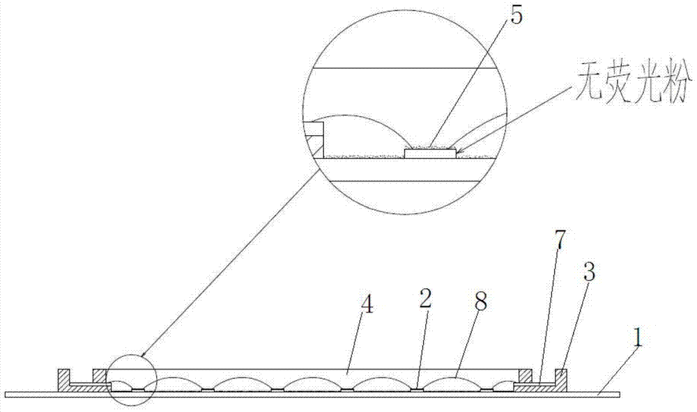
[0023] Such as figure 2 As shown, a COB light source is characterized in that it includes: a heat dissipation substrate 1, a plurality of LED chips 2 are arranged on the heat dissipation substrate 1, and a circle of enclosure 3 is arranged on the outside of the plurality of LED chips 2, and the enclosure 3 is connected to the upper surface of the heat dissipation substrate 1; there is an electrode 7 in the enclosure 3; the LED chip 2 and the electrode 7 are connected by a gold wire 8; the outer surface of the LED chip 2 is covered with a hemisphere Shape cured silica gel 6; a layer of fluorescent powder 5 is uniformly deposited on the outside of the hemispherical cured silica gel 6; the upper surface of the phosphor powder 5 is silica gel 4.

[0024] The heat dissipation substrate 1 is an aluminum substrate.

[0025] The enclosure 3 is made of white silica gel.

[0026] A preparation process for a COB light source, characterized in that it comprises the following steps:

...

Embodiment 2

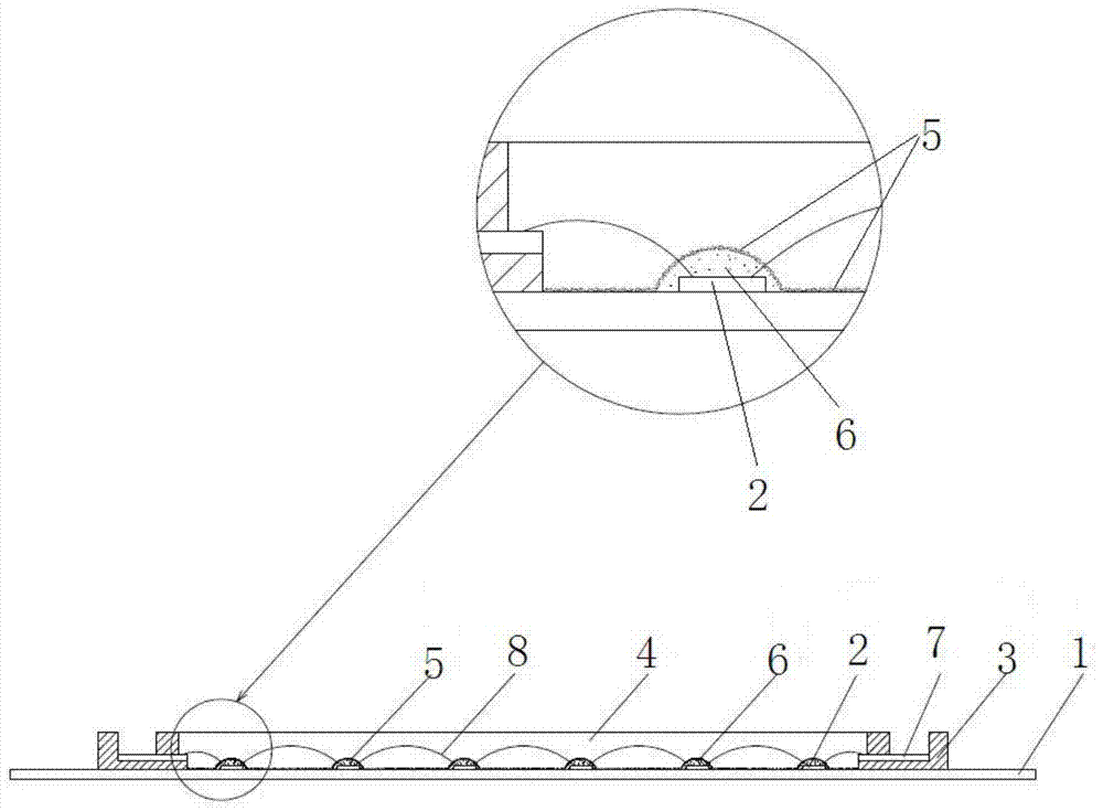
[0033] Such as figure 2 As shown, a COB light source is characterized in that it includes: a heat dissipation substrate 1, a plurality of LED chips 2 are arranged on the heat dissipation substrate 1, and a circle of enclosure 3 is arranged on the outside of the plurality of LED chips 2, and the enclosure 3 is connected to the upper surface of the heat dissipation substrate 1; there is an electrode 7 in the enclosure 3; the LED chip 2 and the electrode 7 are connected by a gold wire 8; the outer surface of the LED chip 2 is covered with a hemisphere Shape cured silica gel 6; a layer of fluorescent powder 5 is uniformly deposited on the outside of the hemispherical cured silica gel 6; the upper surface of the phosphor powder 5 is silica gel 4.

[0034] The heat dissipation substrate 1 is a copper substrate.

[0035] The material of the enclosure 3 is PC material.

[0036] A preparation process for a COB light source, characterized in that it comprises the following steps:

...


PUM


Abstract

The invention discloses a COB (Chip On Board) light source and a preparation process thereof. The COB light source is characterized by comprising a heat dissipation substrate (1), wherein a plurality of LED (Light Emitting Diode) chips (2) are arranged on the heat dissipation substrate (1), a circle of enclosure (3) is arranged outside the plurality of LED chips (2), and the enclosure (3) is connected with the upper surface of the heat dissipation substrate (1); an electrode (7) is arranged inside the enclosure (3); the LED chips (2) are connected with the electrode (7) by a gold thread (8); a hemispherical cured silica gel (6) is wrapped outside the LED chips (2); and a layer of fluorescent powder (5) is uniformly deposited outside the hemispherical cured silica gel (6). According to the COB light source and the preparation process thereof, the fluorescent powder around the LED chips is distributed uniformly, so the light distribution in each direction is uniform; the process is simple, the cost is low, the emission angle is large, the lighting effect is high, the color temperature consistency of the light source is good, and the product quality consistency is good.

Description

technical field [0001] The invention relates to a COB light source and a preparation process thereof, belonging to the technical field of light source production. Background technique [0002] Most of the conventional phosphor precipitation processes are simply achieved by standing at room temperature or accelerating precipitation in a centrifuge. The phosphor precipitation effect is as follows: figure 1 As shown, only the upper surface of the light source chip and the upper surface of the copper substrate are deposited with phosphor powder, but there is no phosphor powder on the side wall of the LED chip, resulting in serious uneven light distribution of the light source chip. If it is left standing at normal temperature, it will take a long time and the production will be inconvenient; if the investment of the centrifuge equipment is large; both effects are not ideal. Contents of the invention [0003] The technical problem to be solved by the present invention is to pr...

Claims


Application Information

Patent Timeline
Patent Type & Authority Patents(China)
IPC IPC(8): H01L33/64H01L33/62H01L33/54H01L33/50H01L33/48
CPCH01L33/48H01L33/50H01L33/54H01L33/62H01L33/64
Inventor 洪春旭王钢
Owner 淮安吉山光电科技有限公司
Why Eureka
Try Eureka