Circuit structure of peak current circuit capable of automatically regulating output voltage

A circuit output and automatic adjustment technology, which is applied in the direction of adjusting electric variable, output power conversion device, DC power input to DC power output, etc. It can solve the problems affecting the normal use of the converter and the damage of the converter, so as to ensure the use The effect of safety, prolonging the service life and reducing the cost of use

Inactive Publication Date: 2015-12-16
李眯眯
View PDF0 Cites 0 Cited by
  • Summary
  • Abstract
  • Description
  • Claims
  • Application Information

AI Technical Summary

Problems solved by technology

However, when the converter works in an abnormal condition, such as a short circuit, it will keep working at the maximum peak current for a long time, which will cause damage to the converter and affect the normal use of the converter

Method used


Image

  • Circuit structure of peak current circuit capable of automatically regulating output voltage

Examples


Embodiment Construction

[0008] The present application will be further described below in conjunction with specific drawings and embodiments.

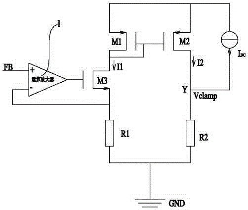
[0009] Such as figure 1 As shown: in order to automatically adjust the output voltage of the peak current circuit, the application includes an operational amplifier 1, the output terminal of the operational amplifier 1 is connected to the gate terminal of the third MOS transistor M3, and the inverting terminal of the operational amplifier 1 is connected to the third The source terminals of the MOS transistor M3 are connected, and the non-inverting terminal of the operational amplifier 1 forms a feedback voltage input terminal FB; the operational amplifier 1 is connected with the third MOS transistor M3 to form a voltage follower. The source terminal of the third MOS transistor M3 is grounded through the first resistor R1, the drain terminal of the third MOS transistor M3 is connected to the drain terminal of the first MOS transistor M1, the gate terminal of t...


PUM


Abstract

The invention relates to a circuit structure of a peak current circuit capable of automatically regulating output voltage. The circuit structure comprises an operational amplifier, an output end of the operational amplifier is connected with a grid end of a third metal oxide semiconductor (MOS) transistor; a source end of the third MOS transistor is connected with an anti-phase end of the operational amplifier and is grounded through a first resistor; a drain end of the third MOS transistor is connected with a drain end of a first MOS transistor, a grid end of the first MOS transistor and a grid end of a second MOS transistor; source ends of the first MOS transistor and the second MOS transistor are correspondingly connected and are connected with a power supply IDC; the power supply IDC is connected with a drain end of the second MOS transistor corresponding to the other end which is connected with the source end of the second MOS transistor; and a drain end of the second MOS transistor is grounded through a second resistor. The circuit structure is simple, regulation is convenient, the use safety of a converter is guaranteed, the service life of the converter is prolonged, the usage cost of the converter is reduced, and the circuit structure is safe and reliable.

Description

technical field [0001] This application relates to a circuit structure, especially a circuit structure for automatically adjusting the output voltage of a peak current circuit, specifically a circuit structure for automatically adjusting the output voltage of a current mode DC-DC converter peak current circuit, which belongs to the current mode The technical field of DC-DC converters. Background technique [0002] DC-DC converters can be divided into voltage mode and current mode according to the feedback mode adopted. Among them, the voltage feedback control is the most basic control technology of the switching power supply, which belongs to the single-loop feedback control method. Voltage feedback control realizes negative feedback of the entire circuit through only one voltage feedback signal, and there is only one feedback loop in the entire control circuit, which is a single-loop control system. Current control can be divided into average current and peak current feed...

Claims


Application Information

Patent Timeline
Patent Type & Authority Applications(China)
IPC IPC(8): H02M3/156
Inventor 李眯眯
Owner 李眯眯
Why Eureka
Try Eureka