
A fast mimo system transmitter precoding method

A transmitter and precoding technology, which is applied in transmission systems, digital transmission systems, radio transmission systems, etc., can solve problems such as difficulty in meeting practical application requirements, large calculation time overhead, and small channel mutual information, so as to reduce calculation time overhead , improve bit error performance, and improve the effect of channel mutual information

Active Publication Date: 2019-01-29
COMBA TELECOM SYST CHINA LTD
View PDF4 Cites 0 Cited by
  • Summary
  • Abstract
  • Description
  • Claims
  • Application Information

AI Technical Summary

Problems solved by technology

However, these precoding methods have shortcomings, such as channel diagonalization, classical water injection and maximum diversity precoding, although the calculation time is small, the channel mutual information achieved is also small, which is difficult to meet the needs of practical applications; Although exhaustive precoding and optimal precoding achieve large channel mutual information, the calculation time overhead is also large, which is difficult to achieve in practical applications.

Method used


Image

  • A fast mimo system transmitter precoding method
  • A fast mimo system transmitter precoding method
  • A fast mimo system transmitter precoding method

Examples


Embodiment

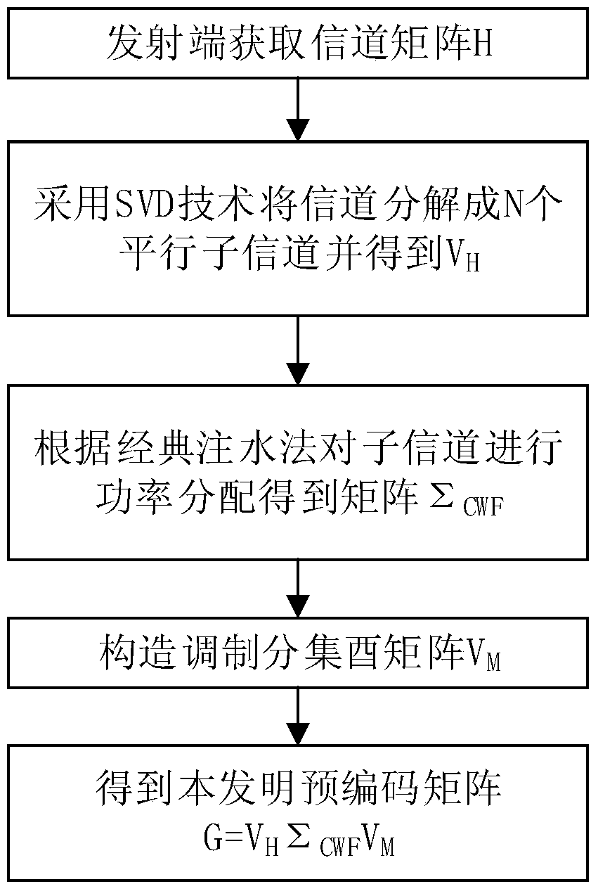
[0034] Such as figure 1 As shown, a fast MIMO system transmitter precoding method, the core is two main steps to obtain the matrix Σ CWF and V M , the ultimate goal is to get the precoding matrix G.

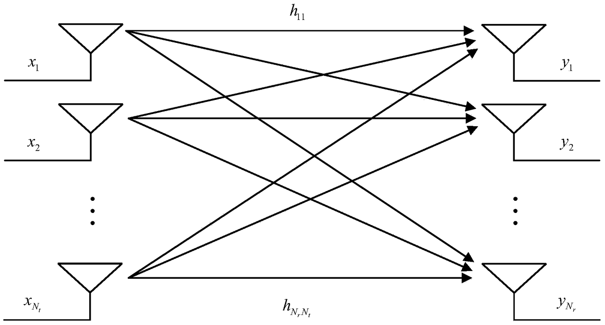
[0035] figure 2 is an N t root transmit antenna and N r The MIMO system channel model of the root receiving antenna, as can be seen from the figure, there are a total of Total N r N t different coupling channels.

[0036] Consider the baseband equivalent model of the MIMO system as: y=HGx+n.

[0037] where x is N t x1 emission complex vector, y is N r ×1 receive complex vector, H is N r ×N t The complex channel matrix, G is N t ×N t The precoding matrix of . Similarly, the SVD decomposition of the precoding matrix G can be obtained:

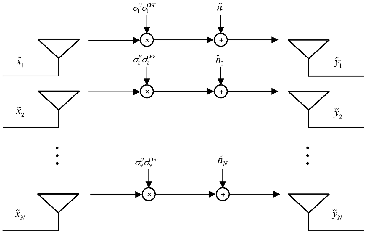
[0038] In the precoding method of the present invention, the left unitary matrix U of the precoding matrix G G Take V H , the diagonal matrix Σ G According to the classical water injection power distribution method, Σ CWF , t...


PUM


Abstract

The invention discloses a fast MIMO system transmitting terminal precoding method, comprising the following steps: S1, using SVD technology to decompose a channel matrix to obtain N parallel sub-channels; S2, carrying out power allocation in view of the signal-to-noise ratio gamma i of the ith sub-channel according to a classic injection method to obtain a power allocation matrix sigma CWF; S3, constituting a modulation diversity unitary matrix VM according to a modulation diversity constellation rotation method to reduce the overlap of constellation points; S4, using a product of an original precoding matrix VH in S1, the matrix sigma CWF in S2 and the matrix VM in S3 as a transmitting terminal precoding matrix, namely, G=VH sigma CWFVM, obtaining the precoding method disclosed by the invention, and using the matrix to transmit signals. The fast MIMO system transmitting terminal precoding method disclosed by the invention is used for reducing the precoding computation time cost, improving the mutual information of the channels and meeting the demands of practical application.

Description

technical field [0001] The invention relates to the technical field of wireless communication, in particular to a precoding method at a transmitting end of a fast MIMO system. Background technique [0002] Multi-antenna technology refers to a comprehensive technology that uses multiple antennas at the transmitting end or receiving end of wireless communication and combines advanced signal processing technology at the same time. If multiple antennas are used simultaneously at the transmitting end and the receiving end, it is called multiple input multiple output technology (MIMO, Multiple Input Multiple Output). MIMO is a major breakthrough in smart antenna technology in the field of wireless communication. It can use space-time block code and space multiplexing code technology to double the capacity and spectrum utilization of the communication system without increasing the bandwidth. [0003] The precoding technology at the transmitting end of the MIMO system requires the ...

Claims


Application Information

Patent Timeline
Patent Type & Authority Patents(China)
IPC IPC(8): H04B7/0456H04L5/00
CPCH04B7/0456H04L5/006
Inventor 柯峰黄晓宇唐大津邓远意麦帆
Owner COMBA TELECOM SYST CHINA LTD
Learn More