
Exchange equipment based on Openflow and ROF and applications thereof

A technology of switching equipment and switching modules, applied in the direction of data switching network, selection device of multiplexing system, optical fiber transmission, etc., to achieve the effect of simplifying remote equipment, reducing the cost of wired use, reducing maintenance and manual configuration

Inactive Publication Date: 2015-12-16
LANGCHAO ELECTRONIC INFORMATION IND CO LTD
View PDF4 Cites 4 Cited by
  • Summary
  • Abstract
  • Description
  • Claims
  • Application Information

AI Technical Summary

Problems solved by technology

[0005] In the prior art, there is no device or method that combines Openflow and RoF for signal switching and forwarding. How to effectively combine Openflow and RoF for switching devices has become a new research topic.

Method used


Image

  • Exchange equipment based on Openflow and ROF and applications thereof
  • Exchange equipment based on Openflow and ROF and applications thereof
  • Exchange equipment based on Openflow and ROF and applications thereof

Examples


Embodiment 1

[0044] Figure 1-3 shown.

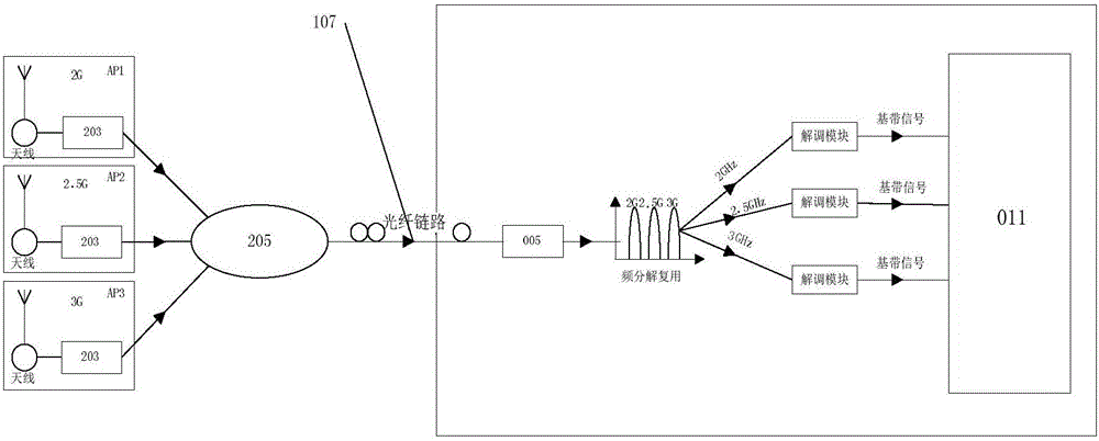
[0045] A switching device based on Openflow and ROF, comprising a controller 004, a switching module 011, a modulation / demodulation module 010, a frequency division multiplexing / demultiplexing module 009, a conversion module and an optical port 007 connected in sequence; the conversion module It includes an electro-optical conversion module 008 and a photoelectric conversion module 006; the controller 004 includes a controller Openflow module; the switching module 011 includes a switching matrix Openflow module and a switching matrix. The controller 004 is integrally connected to the switch module 011, and the photoelectric conversion module 006 and the photoelectric conversion module 008 work in a time division duplex mode. The integrated use of the controller 004 and the switch module 011 reduces the amount of equipment used, makes the switch more powerful, increases the network performance without changing the existing network architecture, and ...

Embodiment 2

[0047] The switching device based on Openflow and ROF as described in Embodiment 1, the difference is that the controller 004 includes a multi-interface module, an API management module, a fault management module and a service management module; the API management module uses a software programming interface Connect with APP module 003. The API management module receives the data from the upper-layer application provider through the software programming interface (API) and compiles and preprocesses the data, and sends it to the controller Openflow module, and the controller Openflow module receives the data from the API management module and Generate a flow table and send it to the switching module 011, or manually write a flow table through the web management interface of this device and send it out; the fault management module performs real-time monitoring of the network, and equipment failure can be automatically switched to the standby device; the service management The mo...

Embodiment 3

[0051] The switching device based on Openflow and ROF according to Embodiment 3, the difference is that the multi-interface module includes a cloud management network interface. The multi-interface module provides a cloud management network interface, through which the manager NMS (Network-Management-System) 002 can centrally manage the network topology.


PUM


Abstract

The invention relates to exchange equipment based on Openflow and ROF and applications thereof. The exchange equipment comprises a controller, an exchange module, a modulation / demodulation module, a frequency division multiplexing / de-multiplexing module, a conversion module and an optical port which are connected in sequence. The conversion module comprises an electric-optical conversion module and an optical-electric conversion module. The controller comprises a controller Openflow module. The exchange module comprises an exchange matrix Openflow module and an exchange matrix. The optical port is used for inputting and outputting optical signals and is externally connected with an optical fiber link. After the exchange matrix Openflow module receives a flow table containing instruction information and sent by the controller, the exchange matrix Openflow module issues an instruction to the exchange matrix, and according to the instruction, the exchange matrix completes corresponding switching action so as to realize data forwarding.

Description

technical field [0001] The invention relates to a switching device based on Openflow and ROF and an application thereof, and belongs to the technical field of network wireless communication devices. Background technique [0002] Openflow technology is a new network application method. Each application provider can formulate its own network strategy privately, making the network more intelligent and flat, changing manual configuration to automatic configuration, and reducing manual overhead and human errors. [0003] The RoF (Radio-Over-Fiber) system uses optical fiber as the transmission link between the base station (BS) and the central station (CS), and directly uses optical carriers to transmit radio frequency signals. The optical fiber only plays the role of transmission, switching, control and signal regeneration are all concentrated in the central station, and the base station only realizes photoelectric conversion. In this way, complex and expensive equipment can be c...

Claims


Application Information

Patent Timeline
IPC IPC(8): H04Q11/00H04L29/08H04L12/24H04B10/2575
Inventor 季伟闫增禄李彬先黄康睿
Owner LANGCHAO ELECTRONIC INFORMATION IND CO LTD
Learn More