Electric coagulation power handle and planing components

A power component and electrocoagulation technology, applied in the field of medical devices, can solve the problems of increasing the difficulty of surgery, increasing the risk of surgery, and small operating space, so as to reduce the difficulty of surgery, avoid waiting time for surgery, and reduce surgical interference.

Active Publication Date: 2018-01-30
CHONGQING XISHAN SCI & TECH
View PDF6 Cites 0 Cited by
  • Summary
  • Abstract
  • Description
  • Claims
  • Application Information

AI Technical Summary

Problems solved by technology

[0002] During minimally invasive tissue cutting, in otolaryngology lesion tissue resection surgery, due to the small operating space, planing components composed of planing knives and planing handles are generally used to resect diseased tissues, which can effectively ensure a more efficient operation. High cutting efficiency; in actual operation, the planing tool is easy to cause wound surface bleeding when planing. In the prior art, a single electric coagulation forceps is generally used for hemostasis, but in the process of replacing the electric coagulation forceps, the operation time is increased. Waiting time, and may delay the best hemostasis time, increasing the risk of surgery; and in order to avoid replacement time, a planing assembly with electrocoagulation and planing functions has appeared, and the output of electrocoagulation current is directly used on the tool assembly. The radial opening is inserted into the power supply and connected to the external power supply wire, which is not conducive to the operation in a narrow space, affects the doctor's operating vision, and increases the difficulty of the operation

Method used


Image

  • Electric coagulation power handle and planing components
  • Electric coagulation power handle and planing components
  • Electric coagulation power handle and planing components

Examples


Embodiment Construction

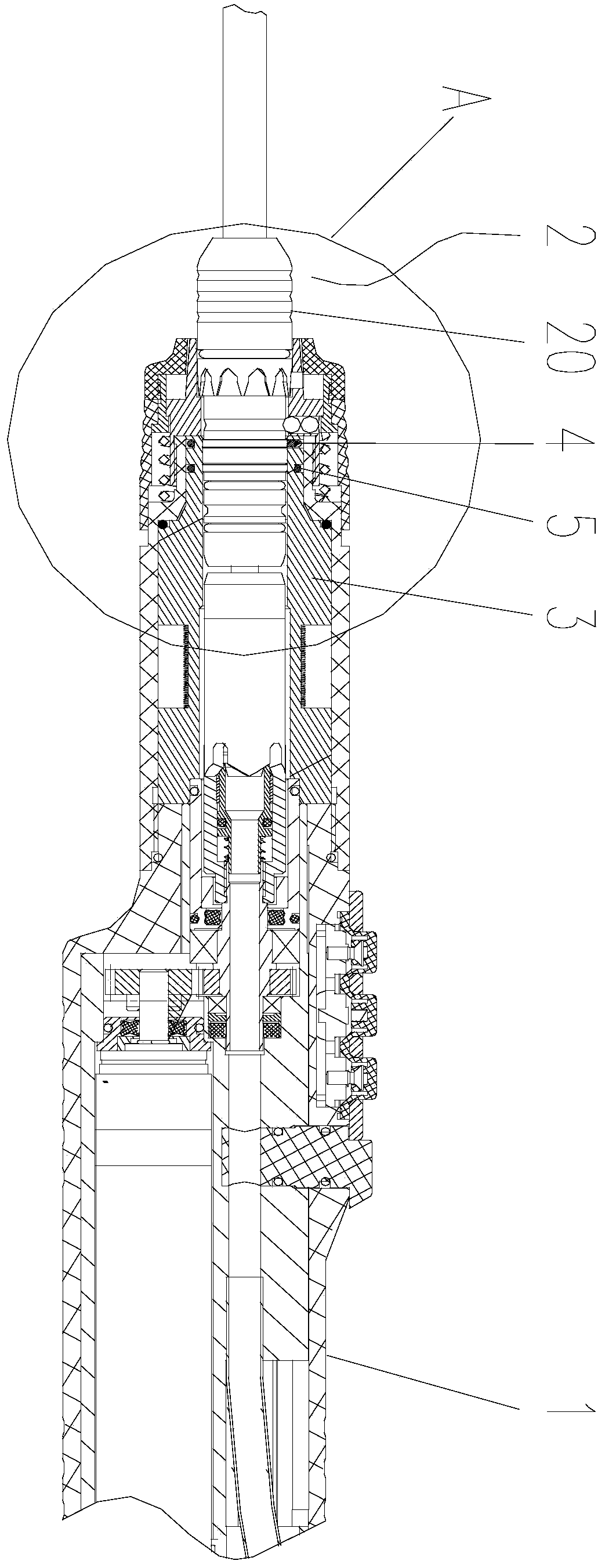
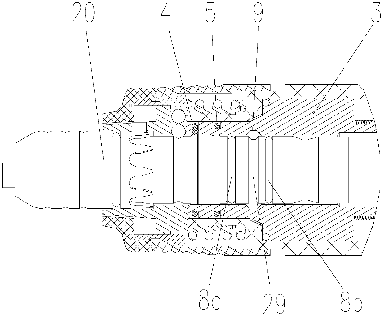
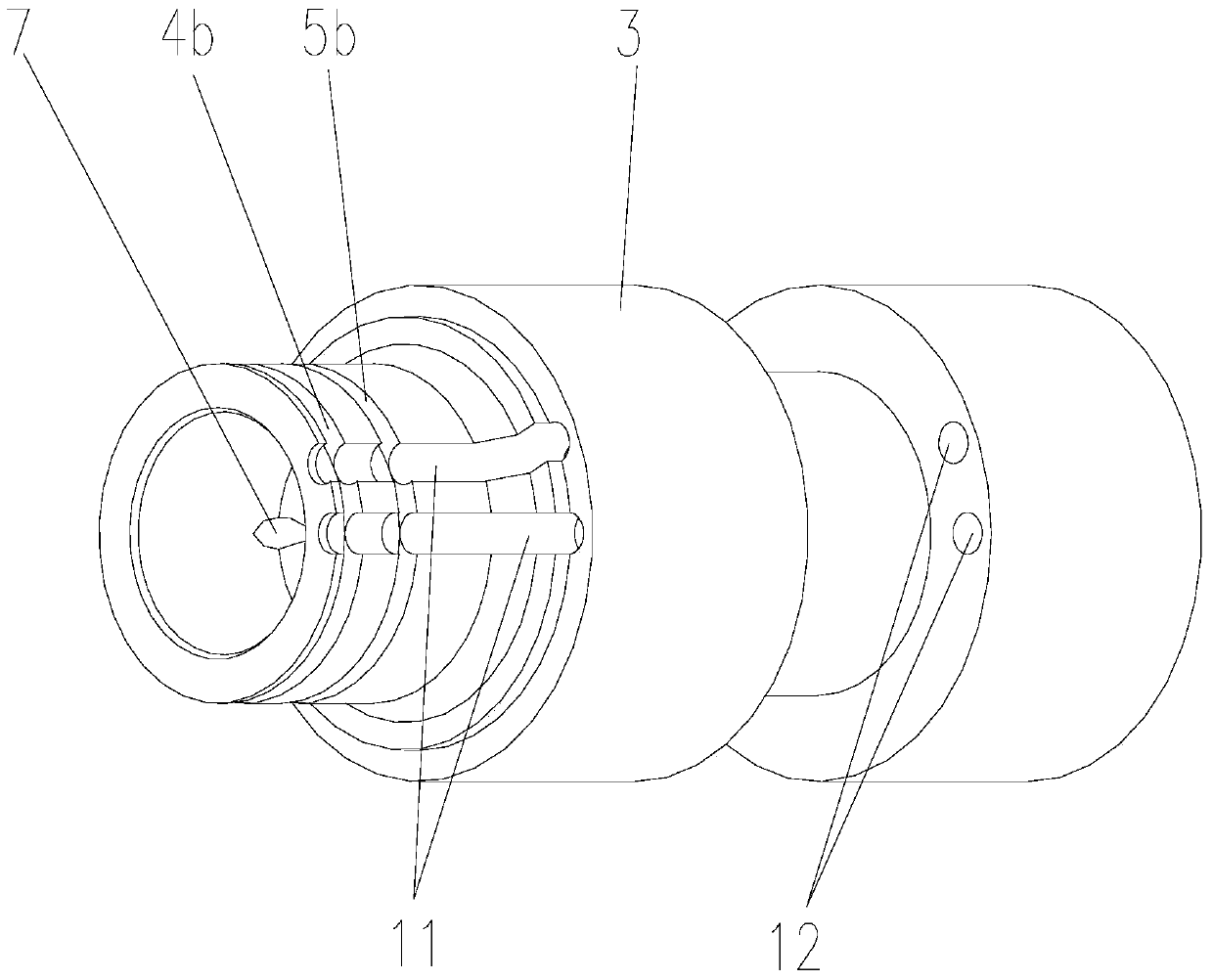
[0024] figure 1 It is a structural schematic diagram of the assembly of the electric coagulation type power handle and the cutter in the planing assembly of the present invention, figure 2 for figure 1 Enlarged view of A in the middle, image 3 It is a structural schematic diagram of the support sleeve of the electric coagulation type power handle of the present invention, Figure 4 It is a structural schematic diagram of the arc-shaped conductive ring of the electric coagulation type power handle of the present invention, Figure 5 It is a structural schematic diagram of the outer cutter tube of the cutter in the planing assembly of the present invention, Image 6 for Figure 5 The magnified view of B, Figure 7 It is a schematic diagram of the assembly structure of the inner and outer cutter tubes of the cutter in the planing assembly of the present invention, Figure 8 It is a schematic diagram of the structure in which the water injection channel in the handle of th...


PUM


Abstract

The invention discloses an electrocoagulation type power handle and a planing assembly, comprising a handle housing and a power assembly, the handle housing has an interface for connecting and driving a tool, and also includes a handle electrocoagulation circuit, the handle electric The coagulation circuit includes an output electrode arranged in the interface. After the tool is installed in the interface, the output electrode is electrically connected to the tool coagulation circuit of the tool; by setting the output electrode at the interface of the handle, when the tool is inserted, it can be directly used for the tool. The electric coagulation circuit inside the tool supplies power to make the coagulation work normally; at the same time, the setting of the handle electric coagulation circuit does not affect the normal installation of the tool, so that the electric coagulation type planing handle has both electric coagulation and planing functions, which can stop bleeding in time and avoid surgery Waiting time, while avoiding external cables on the cutter, to ensure that it will not affect the doctor's surgical operation vision, and will not increase the inconvenience of surgical operation due to the peripheral connection seat or cable connection of the electrocoagulation circuit, reduce surgical interference, and reduce surgical difficulty. .

Description

technical field [0001] The invention relates to a medical device, in particular to a medical electric coagulation power handle and a planer assembly for minimally invasive tissue cutting. Background technique [0002] During minimally invasive tissue cutting, in otolaryngology lesion tissue resection surgery, due to the small operating space, planing components composed of planing knives and planing handles are generally used to resect diseased tissues, which can effectively ensure a more efficient operation. High cutting efficiency; in actual operation, the planing tool is easy to cause wound surface bleeding when planing. In the prior art, a single electric coagulation forceps is generally used for hemostasis, but in the process of replacing the electric coagulation forceps, the operation time is increased. Waiting time, and may delay the best hemostasis time, increasing the risk of surgery; and in order to avoid replacement time, a planing assembly with electrocoagulation...

Claims


Application Information

Patent Timeline
Patent Type & Authority Patents(China)
IPC IPC(8): A61B18/12
Inventor 郭毅军张新云张金彬
Owner CHONGQING XISHAN SCI & TECH
Why Eureka
Try Eureka