Industrial dust remover

An industrial dust collector and base plate technology, which is applied in chemical instruments and methods, dispersed particle separation, combined devices, etc., can solve the problems affecting the efficiency of equipment dust removal, increase the labor intensity of users, shorten the service life of equipment, etc., and achieve effective filtration Dust removal, maintaining purification and dust removal effect, good effect of dust removal effect

Active Publication Date: 2015-12-23
YANCHENG LANFENG ENVIRONMENTAL ENG TECH
View PDF5 Cites 9 Cited by
  • Summary
  • Abstract
  • Description
  • Claims
  • Application Information

AI Technical Summary

Problems solved by technology

[0003] Chinese patent CN204412703 discloses an industrial particle suction dust collector, which includes a volute cyclone collector connected with a suction pipe and a cabinet-type purification treatment device connected to the air outlet of the collector. The discharge port is connected with a discharge hopper and a material receiving belt in turn. The purification treatment device includes a cabinet, a cyclone dust collector placed in the cabinet and connected in sequence, an air purification filter and a vortex fan. The lower end of the cyclone dust collector is connected with a The dust collection hopper, the air inlet of the cyclone dust collector is connected with the air outlet of the cyclone collector. When the granular material is sucked through the feeding hopper, the negative pressure generated by the high-pressure vortex fan will suck the material into the volute cyclone collector at a high speed. The effect of cyclone separation makes the coarse particles fall directly into the feeding belt, while the fine particles enter the cyclone dust collector, and fall directly into the fine hopper after separation, and the dust enters the air treatment room and is filtered by high-efficiency filter cotton, and settles on the filter cotton. The air enters the vortex fan and is discharged into the atmosphere through the vortex fan. However, when it is in use, the user needs to hold the suction pipe and align it with the position where dust needs to be removed. When the position where dust needs to be removed is high, it will undoubtedly increase the labor of the user. At the same time, it is impossible to effectively clean the inside of the equipment, because when the equipment is used for particle suction and dust removal, a large amount of dust will often be deposited in the equipment, which will affect the efficiency of dust removal and shorten the service life of the equipment when used for a long time , and no water is used for purification and dust removal, so that the final collected dust is still relatively dry, and it is easy to be blown up and become dust again, resulting in secondary pollution and affecting the dust removal effect

Method used


Image

  • Industrial dust remover

Examples


Embodiment Construction

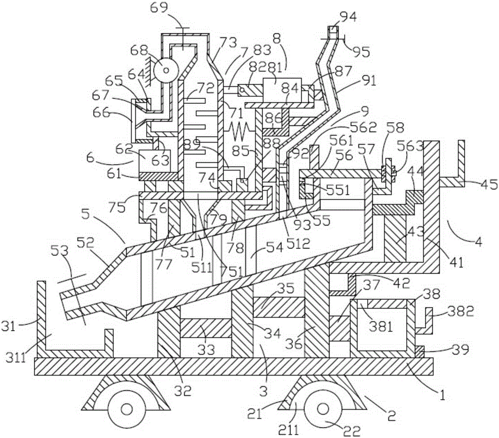
[0020] like figure 1 As shown, the industrial dust collector of the present invention includes a base plate 1, a roller device 2 located below the base plate 1, a support device 3 located above the base plate 1, a gripping device 4 located above the support device 3, and a The humidification device 5 above the support device 3, the filter device 7 above the humidifier 5, the air intake device 6 on the left side of the filter device 7, the shaking device 8 on the right side of the filter device 7 and The air outlet device 9 on the right side of the rocking device 8 .

[0021] like figure 1 As shown, the base plate 1 is in the shape of a cuboid, and the base plate 1 is placed horizontally.

[0022] like figure 1 As shown, there are two roller devices 2 located on the left and right sides respectively. The roller device 2 includes a first support block 21 and a roller 22 located below the first support block 21 . The cross-section of the first support block 21 is an isosceles...


PUM


Abstract

The invention discloses an industrial dust remover. The industrial dust remover comprises a bottom plate, rolling wheel devices, a supporting device, a holding device, a humidifying device, a filtering device, an air inlet device, a shaking device and an air outlet device. The rolling wheel devices comprise first supporting blocks (21) and rolling wheels (22), the supporting device comprises a collecting box (31), a first supporting rod (32), a first transverse rod (33), a second supporting rod (34), a second transverse rod (35), a third supporting rod (36), a third transverse rod (37), a water tank (38) and a first fixing block (39), the holding device (4) comprises a first fixing frame (41), a second fixing frame (42), a fourth supporting rod (43), a first connecting rod (44) and a second holding rod (45), and the humidifying device (5) comprises a frame (51) and a discharging hopper (52). Particle sucking and dust removing can be effectively performed on air entering the device, and dust is convenient to collect.

Description

technical field [0001] The invention relates to the technical field of environmental protection, in particular to an industrial dust collector. Background technique [0002] With the large-scale development of the steel, abrasives, and refractory industries, the industrial dust and waste cleaning produced have endangered the production environment and production efficiency. At present, there is no ideal special equipment for timely cleaning of waste generated in production. [0003] Chinese patent CN204412703 discloses an industrial particle suction dust collector, which includes a volute cyclone collector connected with a suction pipe and a cabinet-type purification treatment device connected to the air outlet of the collector. The discharge port is connected with a discharge hopper and a material receiving belt in turn. The purification treatment device includes a cabinet, a cyclone dust collector placed in the cabinet and connected in sequence, an air purification filter ...

Claims


Application Information

Patent Timeline
Patent Type & Authority Applications(China)
IPC IPC(8): B01D50/00
Inventor 徐自强
Owner YANCHENG LANFENG ENVIRONMENTAL ENG TECH
Why Eureka
Try Eureka