
Flue gas denitration device for carbon pot calciner and denitration technology of flue gas denitration device

A tank-type calciner and calciner technology, which is applied to the separation of dispersed particles, chemical instruments and methods, separation methods, etc., to achieve the effect of ensuring safe and economical operation

Inactive Publication Date: 2015-12-23
SUNSTONE DEV
View PDF8 Cites 6 Cited by
  • Summary
  • Abstract
  • Description
  • Claims
  • Application Information

AI Technical Summary

Problems solved by technology

[0004] Aiming at the problems of the existing SNCR denitrification device, the present invention provides a carbon tank type calciner flue gas denitrification device and its denitrification process in combination with the characteristics of the flue gas of the carbon calciner

Method used


Image

  • Flue gas denitration device for carbon pot calciner and denitration technology of flue gas denitration device

Examples


Embodiment Construction

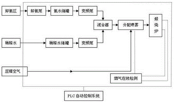
[0014] As shown in the figure, a carbon tank type calciner flue gas denitration device is mainly composed of ammonia water storage system, ammonia water delivery system, ammonia water dilution system, reducing agent injection system in front of the furnace, calciner, PLC control system and flue gas online detection system The ammonia water storage system includes the ammonia discharge pump and the ammonia water storage tank, the ammonia water delivery system includes two frequency conversion pumps, the ammonia water dilution system includes the dilution water storage tank, the frequency conversion pump and the mixer, and the reductant furnace front injection system consists of a distribution spray mechanism and cooling The air supply mechanism consists of several spray guns, and the spray guns are arranged on the flue at the outlet of the calciner. The cooling air supply mechanism includes a compressed air generator, and the air duct of the compressed air generator communicates ...


PUM


Abstract

The invention provides a flue gas denitration device for a carbon pot calciner and a denitration technology of the flue gas denitration device. The flue gas denitration device mainly comprises an ammonia water storage system, an ammonia water conveying system, an ammonia water dilution system, a reducing agent furnace-front injection system, the calciner, a PLC (programmable logic controller) control system and an on-line flue gas detecting system, wherein 20% of ammonia water is selected as a reducing agent for denitration of carbon calcination flue gas, a denitration reaction window is set to be at the temperature of 850-950 DEG C, the reaction position is selected to be in a convergent flue duct at an outlet of the calciner, the ammonia escape content is monitored in real time at the outlet of the calciner and is controlled to be smaller than 8 mg / Nm3, and the ammonia injection amount is controlled effectively. An SNCR (selective non-catalytic reduction) denitration technology is adopted and combined with characteristics of the carbon calciner flue gas so as to be successfully applied to denitration treatment of calcination flue gas, sequential automatic start-up and shutdown of the flue gas denitration system for the carbon pot calciner and automatic detection and storage of operation parameters are realized, key parameters are adjusted automatically, automatic control of the denitration system is realized, and safe and economical operation of flue gas denitration equipment is guaranteed.

Description

technical field [0001] The invention relates to the technical field of carbon environmental protection equipment for aluminum, in particular to a flue gas denitrification device of a carbon tank type calciner and a denitrification process thereof. Background technique [0002] With the increasingly stringent national environmental protection requirements, the emission requirements for nitrogen oxides are also getting higher and higher, and the denitrification of flue gas from carbon production has been put on the agenda. SNCR denitrification technology refers to selective non-catalytic reduction. This technology generally uses anhydrous ammonia, urea or hydrogen acid in the furnace as a reducing agent to reduce NOx. Since this process does not use a catalyst, it is necessary to add a reducing agent in the high temperature zone. area, rapidly thermally decomposes into NH3, and reacts with NOx in the flue gas to generate N2 and water. Among the reducing agents currently used...

Claims


Application Information

Patent Timeline
IPC IPC(8): B01D53/78B01D53/56
Inventor 周国景张守俊陈长声崔正华
Owner SUNSTONE DEV
Learn More