
Tooth crown drill bit locked through two screws in V-shaped positioning groove

A technology of positioning grooves and locking teeth, which is applied in the direction of drill repair, drilling tool accessories, drilling/drilling equipment, etc., can solve the problems of high production cost and complex structure, and achieve low production cost, large contact area, and improved The effect of carrying capacity

Inactive Publication Date: 2015-12-23
SUZHOU AHNO PRECISION CUTTING TECH CO LTD
View PDF6 Cites 1 Cited by
  • Summary
  • Abstract
  • Description
  • Claims
  • Application Information

AI Technical Summary

Problems solved by technology

These positioning and locking methods have their own characteristics, but most of them have complex structures and high production costs.

Method used


Image

  • Tooth crown drill bit locked through two screws in V-shaped positioning groove
  • Tooth crown drill bit locked through two screws in V-shaped positioning groove
  • Tooth crown drill bit locked through two screws in V-shaped positioning groove

Examples


Embodiment Construction

[0029] Below in conjunction with accompanying drawing, technical solution of the present invention will be further described:

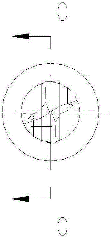
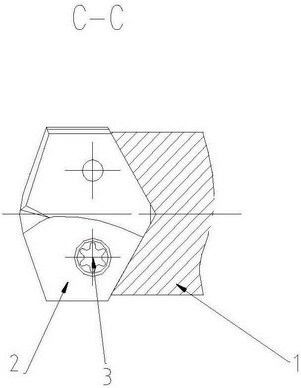
[0030] Such as Figure 1~4 As shown, the double-screw locking crown drill bit in the V-shaped positioning groove includes a drill rod 1, a crown blade 2, and a compression screw 3. The drill rod 1 includes a working part 5 and a neck that are successively connected around the same central axis. part 6 and shank 7, the working part is provided with a spiral chip flute 8, the solid part outside the chip flute 8 is the back 9, and the edge 4 is formed near the chip flute, and the edge 4 is one with the chip removal The helical surface with the same lead of the groove; the shank 7 is in the shape of a cylinder; the neck 6 is a combination of a cone and a cylinder.

[0031] Such as Figure 4~7 As shown, the axial position of the drill pipe is provided with a straight-through main cooling hole 10, and two sub-cooling holes 11 are provided at the left end ...


PUM


Abstract

The invention relates to a tooth crown drill bit locked through two screws in a V-shaped positioning groove. The tooth crown drill bit comprises a drill rod, a tooth crown blade and the compression screws. A through main cooling hole is formed in the position of the axis of the drill rod. The left end of a working part is provided with two branch cooling holes. The main cooling hole and the two branch cooling holes form a Y-shaped internal cooling structure. The end face of the working part of the drill rod is provided with a blade mounting groove. The bottom of the blade mounting groove is provided with a V-shaped positioning surface used for positioning the tooth crown blade. The two sides of the blade mounting groove serve as blade mounting surfaces. A fastening screw hole used for being matched with the corresponding compression screw in a screwed mode is perpendicularly formed in each blade mounting surface. The right end of the tooth crown blade is provided with a V-shaped positioning surface matched with the positioning surface of the working part of the drill rod. The tooth crown blade is provided with stepped holes used for installation of the compression screws. The axis of each stepped hole is perpendicular to the corresponding blade mounting surface. The stepped holes are opposite to the fastening screw holes in position. The tooth crown blade is fastened onto the drill rod through the compression screws. The connection strength of the tooth crown blade and a cutter body is improved through in-groove locking.

Description

technical field [0001] The invention relates to a double-screw locking crown drill bit in a V-shaped positioning groove. Background technique [0002] The crown drill bit is a combined drill bit in which the head is made of cemented carbide or other high-performance materials, and the drill rod is made of alloy steel. It has the advantages of low cost of use and large processing range. [0003] At present, there are many combinations of the head and the drill pipe of the crown drill bit. For example, there are "column pin positioning, screw through locking", "broken line groove positioning, positive and negative buckle screw locking", "cross V-shaped surface positioning, rear pull screw locking", "open pin positioning, non-screw rotation Clamping" and many other forms. These positioning and locking methods have their own characteristics, but most of them have complex structures and high production costs. Contents of the invention [0004] The purpose of the present inv...

Claims


Application Information

Patent Timeline
Patent Type & Authority Applications(China)
IPC IPC(8): B23B51/00B23B51/06
CPCB23B51/00B23B51/06B23B2251/408B23B2251/50
Inventor 刘伟蒋长青叶鑫王晓琴
Owner SUZHOU AHNO PRECISION CUTTING TECH CO LTD
Learn More