
Numerical control rotary table

A technology of rotary workbench and workbench, which is applied in the direction of manufacturing tools, metal processing equipment, metal processing machinery parts, etc., can solve the problems of low reliability and low precision, achieve reliable work, high precision, and improve indexing precision Effect

Inactive Publication Date: 2015-12-23
YANTAI TUOFU NUMERICAL CONTROL MACHINE TOOL
View PDF5 Cites 13 Cited by
  • Summary
  • Abstract
  • Description
  • Claims
  • Application Information

AI Technical Summary

Problems solved by technology

[0003] The existing CNC rotary table has low precision and low reliability, and the rotary table used by hard rail and line rail machine tools is greatly restricted by the guide rail structure

Method used


Image

  • Numerical control rotary table

Examples


Embodiment

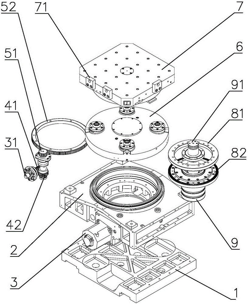
[0021] Such as figure 1 As shown, a numerically controlled rotary workbench includes a connection plate 1 placed on the guide rail of the machine tool, a gearbox 2 is fixed on the connection plate 1, a motor 3 is provided on one side of the gearbox 2, and the output shaft 31 of the motor is in a horizontal direction. The output shaft 31 passes through the side wall of the gearbox 2, enters the inner cavity of the gearbox and is connected to the worm gear; the output shaft 31 drives the worm 41 to rotate, and the worm gear 42 drives a reduction gear set to rotate, and the reduction gear set includes a driving gear 51 and a driven gear 52 , the axis of the driven gear 52 is perpendicular to the horizontal plane, the upper end of the driven gear 52 is fixed with a workbench support body 6, and a workbench is fixed above the workbench support body 6; a locking mechanism is installed in the middle of the driven gear, and the locking mechanism includes a fixed On the upper ratchet p...


PUM


Abstract

The invention discloses a numerical control rotary table. The numerical control rotary table comprises a connection plate arranged on a guide rail of a machine tool, a gear box is fixed on the connection plate, a motor is arranged on one side of the gear box, and an output shaft of the motor is in the horizontal direction and penetrates through a side wall of the gear box to enter an inner cavity of the gear box and to be connected with a worm gear and a worm; the output shaft drives the worm to rotate, the worm gear drives a reduction gear unit to rotate, the reduction gear unit comprises a driving gear and a driven gear, the axis of the drive gear is perpendicular to the horizontal surface, a working table supporting body is fixed at the upper end of the driven gear, and a working table is fixed above the working table supporting body; a locking mechanism is arranged in the middle of the driven gear in a penetration manner and comprises an upper hirth coupling fixed at the bottom end of the working table supporting body and a lower hirth coupling fixed on a hydraulic cylinder, and the working table supporting body can move up and down under pushing of a piston shaft of the hydraulic cylinder. The numerical control rotary table is high in precision and reliability.

Description

technical field [0001] The invention relates to the field of numerical control machine tools, in particular to a numerical control rotary workbench. Background technique [0002] CNC rotary table is a common component of CNC milling machine, often used as a servo axis of CNC milling machine, that is, the C axis of vertical CNC milling machine and the B axis of horizontal CNC milling machine. The CNC rotary table is suitable for continuous rotary processing and multi-face processing of plate and box workpieces, controlled by a CNC system. [0003] The existing CNC rotary table has low precision and low reliability, and the rotary table used in hard rail and line rail machine tools is greatly restricted by the structure of the guide rail. [0004] Therefore, designing a new type of CNC rotary table with high precision and high reliability is a technical problem to be solved in this field. Contents of the invention [0005] The technical problem to be solved by the present ...

Claims


Application Information

Patent Timeline
Patent Type & Authority Applications(China)
IPC IPC(8): B23Q1/30B23Q1/64B23Q16/02
CPCB23Q1/30B23Q1/64B23Q16/065B23Q2701/025
Inventor 万太学刘院升刘兴峰姜文华
Owner YANTAI TUOFU NUMERICAL CONTROL MACHINE TOOL
Learn More