Adsorbing base plate of wall-climbing robot
A wall-climbing robot and chassis technology, applied in the field of robots, can solve problems such as hidden safety hazards, long construction period, and high labor intensity, and achieve the effect of shortening construction period, reducing operating costs, and reducing labor intensity
- Summary
- Abstract
- Description
- Claims
- Application Information
AI Technical Summary
Problems solved by technology
Method used
Image
Examples
Embodiment 1
[0029] Embodiment 1: the rear end of the above-mentioned frame 1 is equipped with a driving shaft, the driving shaft is fixedly mounted with a driving sprocket, the front end of the frame 1 is mounted with a driven shaft, and the driven shaft is fixedly mounted with a driven sprocket. It is a chain, and the chain is installed on the driving sprocket and the driven sprocket. The rear end of the frame 1 is fixedly equipped with a servo reducer, and the power output end of the servo reducer is connected with the power input end of the drive shaft. The adsorption chassis of the wall-climbing robot described in this embodiment adopts a single crawler belt and is driven by a sprocket chain, so the structure is simple and the cost is low. The servo reducer drives the driving sprocket to rotate, the driving sprocket drives the driven sprocket to rotate through the chain, and the chain drives the magnetic variable adsorption unit 2 to rotate, thereby realizing the walking and other ma...
Embodiment 2
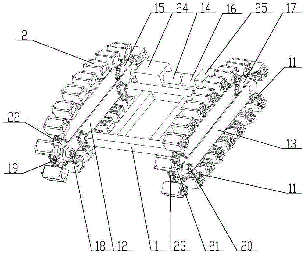
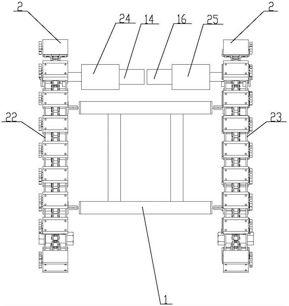
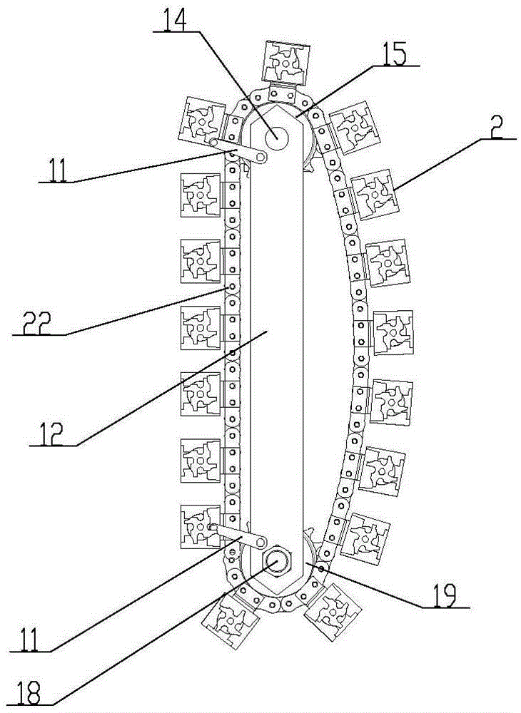
[0030] Embodiment two: the left side of above-mentioned frame 1 is fixedly installed with left wing plate 12, and the right side of frame 1 is fixedly installed with right side wing plate 13, and the rear end of left side wing plate 12 is connected with the right side wing plate 13. A drive shaft is installed between the rear ends, the left end of the drive shaft is fixedly equipped with the first driving sprocket 15, and the right end of the drive shaft is fixedly equipped with the second driving sprocket 17; Shaft 18, the first driven sprocket 19 is fixedly installed on the first driven shaft 18, the second driven shaft 20 is installed on the front end of the right wing plate 13, and the second driven shaft 20 is fixedly installed on the second driven shaft 20. Driven sprocket 21; Track comprises first chain 22 and second chain 23, and first chain 22 is installed on the first driving sprocket 15 and the first driven sprocket 19, and second chain 23 is installed on the secon...
Embodiment 3
[0031] Embodiment three: as attached figure 1 , 2 , 3, 4, 5, 6, 7, and 8, the left side of the above-mentioned frame 1 is fixedly equipped with a left wing 12, and the right side of the frame 1 is fixedly equipped with a right side wing 13, and the left side wing The rear end of 12 is equipped with the first driving shaft 14, is fixedly installed with the first drive sprocket 15 on the first driving shaft 14, and the rear end of right wing plate 13 is equipped with the second driving shaft 16, on the second driving shaft 16 The second driving sprocket 17 is fixedly installed; the front end of the left wing plate 12 is equipped with the first driven shaft 18, and the first driven sprocket 19 is fixedly installed on the first driven shaft 18, and the right side wing plate 13 The front end is equipped with a second driven shaft 20, and a second driven sprocket 21 is fixedly installed on the second driven shaft 20; the track includes a first chain 22 and a second chain 23, an...
PUM
 Abstract
Description
Claims
Application Information
 - R&D
- Intellectual Property
- Life Sciences
- Materials
- Tech Scout
- Unparalleled Data Quality
- Higher Quality Content
- 60% Fewer Hallucinations
Browse by: Latest US Patents, China's latest patents, Technical Efficacy Thesaurus, Application Domain, Technology Topic, Popular Technical Reports.
© 2025 PatSnap. All rights reserved.Legal|Privacy policy|Modern Slavery Act Transparency Statement|Sitemap|About US| Contact US: help@patsnap.com


