Novel lever block structure

A lever hoist, a new type of technology, applied in portable lifting devices, hoisting devices, etc., can solve the problems of time-consuming and laborious operation, complex structure, poor guiding effect, etc., and achieve convenient and fast operation, convenient and comfortable operation, and force distribution. superior effect

Active Publication Date: 2015-12-23
南通碧水新材料科技有限公司
View PDF11 Cites 6 Cited by
  • Summary
  • Abstract
  • Description
  • Claims
  • Application Information

AI Technical Summary

Problems solved by technology

Due to the small size and light weight of the lever block, it is very convenient to carry and operate, and it is suitable for heavy objects with a small tonnage. The existing lever block, due to its own structure, is not optimized for force distribution, and its load capacity is still low. Not strong enough, not stable enough or smooth enough during operation, easy to cause damage to the load or the lever hoist itself during the operation process, the service life is not long enough, the structure is generally more complicated, the operation is time-consuming and laborious, and the switching of the working state is not flexible enough. The braking effect is not good, and the force distribution of the chain guide device is not optimized enough, the load capacity is not strong enough, and the operation is not stable enough or smooth enough. The operation process is easy to cause damage to the load or the lever hoist itself. The service life is not long enough, the guiding performance is poor, the guiding effect is not good, and it is easy to increase the deflection, which not only affects the operation but also has potential safety hazards. The comfort is not high, it is easy to deform, and it is easy to interfere with the components of the lever hoist, causing unnecessary damage

Method used


Image

  • Novel lever block structure
  • Novel lever block structure
  • Novel lever block structure

Examples


Embodiment Construction

[0031] The following specific examples are only explanations of the present invention, and it is not a limitation of the present invention. Those skilled in the art can make modifications without creative contribution to the present embodiment as required after reading this specification, but as long as they are within the rights of the present invention All claims are protected by patent law.

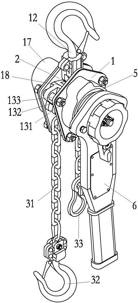
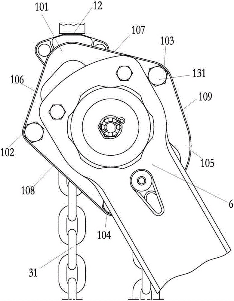
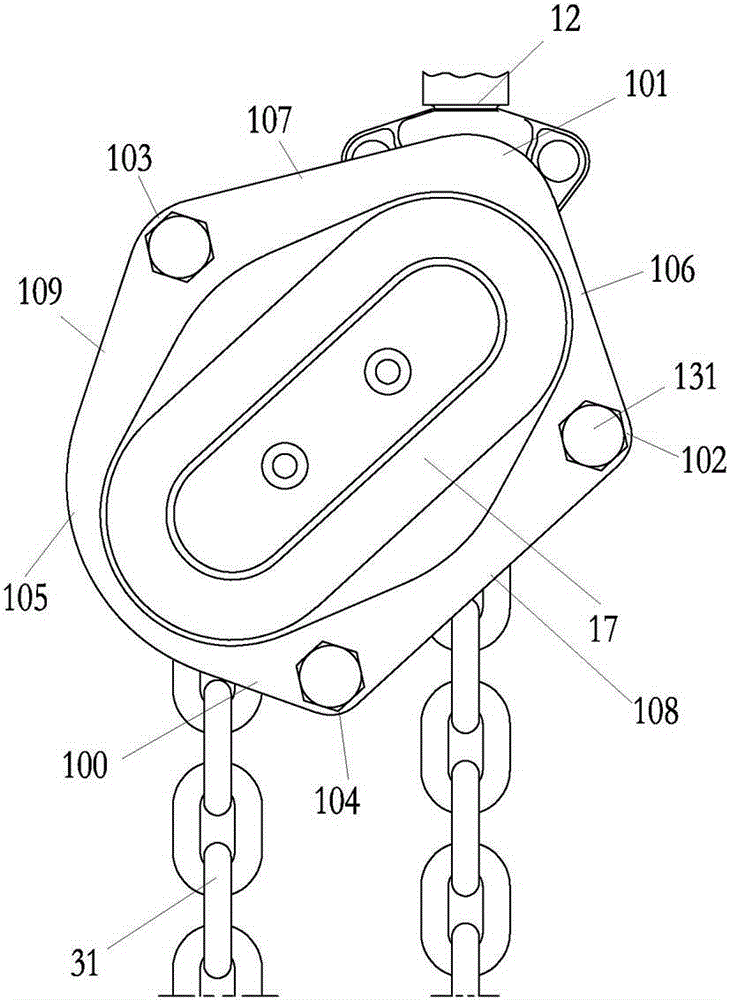
[0032] Examples such as figure 1 , 2 , 3, 4, 5, 6, 7, 8, 9, 10, 11, 12, 13, and 14, the new lever hoist structure includes a front wall panel 1 and a rear wall panel 2 that are set opposite to each other at intervals. A hoisting sprocket 3 is provided between the front wallboard 1 and the rear wallboard 2, and the long axis 4 protruding forward and backward is connected to the lifting sprocket 3, and the long axis 4 is located on the front wallboard. The front side of 1 is connected with a clutch device 5, and the clutch device 5 is provided with a wrench device 6 connected wit...


PUM


Abstract

The invention relates to the technical field of hoisting equipment, particularly to a novel lever block structure which comprises a front wallboard and a back wallboard, wherein the front wallboard and the back wallboard are oppositely arranged at an interval front and back; a hoisting chain wheel is arranged between the front wallboard and the back wallboard; a long shaft stretching out in the front-back direction is connected onto the hoisting chain wheel; a clutch device is arranged at a position, on the front side of the front wallboard, of the long shaft; a wrench device connected with the front wallboard and matched with the clutch device is arranged outside the clutch device; an upper support rod is connected with a part above the hoisting chain wheel between the front wallboard and the back wallboard and is connected with a pothook; a hoisting chain hanging down below the left side and the right side is reeled on the hoisting chain wheel; one end of one of the left side and the right side of the hoisting chain is used as a load end and connected with a lifting hook, and one end of the other of the left side and the right side of the hoisting chain is used as a loose end and connected with a limiting pull ring; a guide chain device is further arranged between the front wallboard and the back wallboard. The novel lever block structure is safe and stable to use, high in carrying capacity and smoothness, excellent in guiding effect, and unlikely to be damaged.

Description

Technical field [0001] The present invention involves the technology field of lifting equipment, which is specifically for the new type of gourd structure. Background technique [0002] Hand tie gourds are manually touched the wrench manually, and the principle of leverage is used to obtain a straight line traction that matches the load, thereby driving heavy objects to move up and down.Due to the small size and light weight of the gourd in the hand, it is very convenient to carry and operate. It is suitable for a smaller tonnage heavy object. The existing hand pulling gourd. Due to the structure of its own structure, the distribution of the force is not optimized.It is not strong enough, it is not stable enough or smooth enough at runtime. The operation process is easy to cause damage to the load or hand to pull the gourd itself. The service life is not long enough. The structure is generally more complicated. The operation is more time -consuming and laborious.The braking effec...

Claims


Application Information

Patent Timeline
Patent Type & Authority Applications(China)
IPC IPC(8): B66D3/12
Inventor 范丽平祝跃进王红华杨卫波
Owner 南通碧水新材料科技有限公司
Why Eureka
Try Eureka