A two-way limit mechanism of laminated U-shaped steel plates

A two-way limit and U-shaped technology, which is applied to building components, earthquake resistance, etc., can solve the problems that the tensile capacity of the limit device cannot be exerted, the hard steel U-shaped steel plate is brittle, and the waste of resources is not easy to yield. , improve the anti-seismic performance, and save the effect of the limiter

Inactive Publication Date: 2018-04-17
BEIJING UNIV OF CIVIL ENG & ARCHITECTURE
View PDF8 Cites 0 Cited by
  • Summary
  • Abstract
  • Description
  • Claims
  • Application Information

AI Technical Summary

Problems solved by technology

Traditional limit devices, whether elastic limit devices or rigid limit devices, can only provide thrust, and the tensile capacity of the limit devices cannot be exerted, resulting in waste of resources
The U-shaped steel plate can be used as a stopper, but the soft steel U-shaped steel plate is easy to yield after being collided, and the hard steel U-shaped steel plate is easily brittle after being collided

Method used


Image

  • A two-way limit mechanism of laminated U-shaped steel plates
  • A two-way limit mechanism of laminated U-shaped steel plates
  • A two-way limit mechanism of laminated U-shaped steel plates

Examples


example 1

[0020] Example 1, directly used on the side of the rubber bearing:

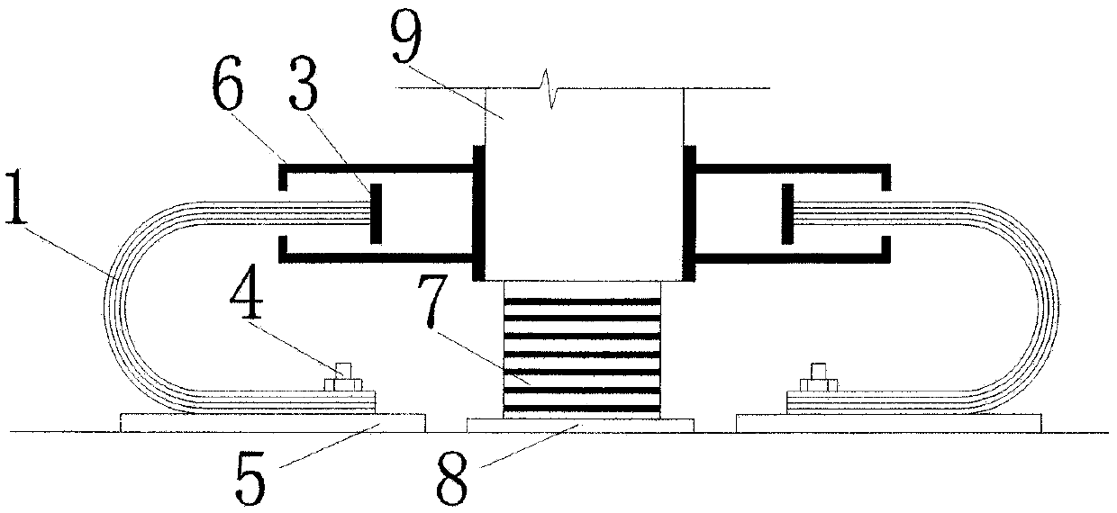
[0021] Such as figure 1 As shown, a bidirectional limit mechanism of laminated U-shaped steel plates includes laminated U-shaped steel plates (1), U-shaped steel plate fixing plates (5), push-pull plates (3), push-pull grooves (6) and the like.

[0022] (1) Fix the push-pull groove (6) on the side of the upper structural column of the rubber bearing. If the column is a steel column, the push-pull groove can be directly welded to the column. If the column is a concrete column, it can be pre-embedded on the column Connect the bolts, and fix the connection slots with bolts.

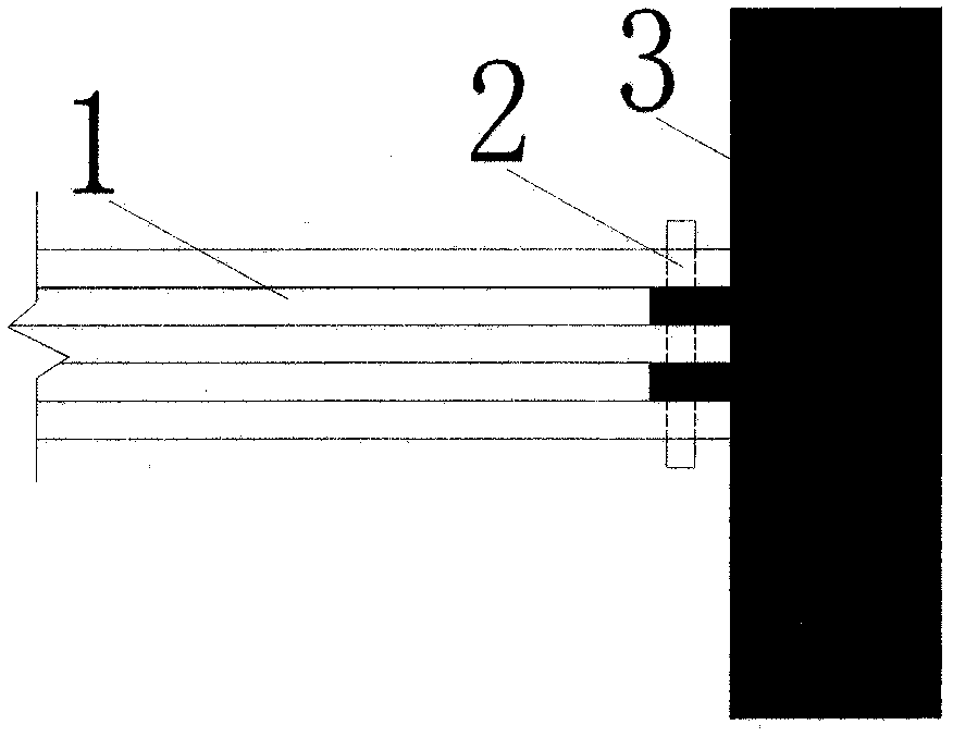
[0023] (2) The push-pull plate (3) is fixed on the horse-toothed bracket of the upper arm of the laminated U-shaped steel plate (1) by its connection key with the connection bolt (2).

[0024] (3) Put the upper arm of the laminated U-shaped steel plate (1) together with the push-pull plate (3) into the connection groove (6) from the side ...

example 2

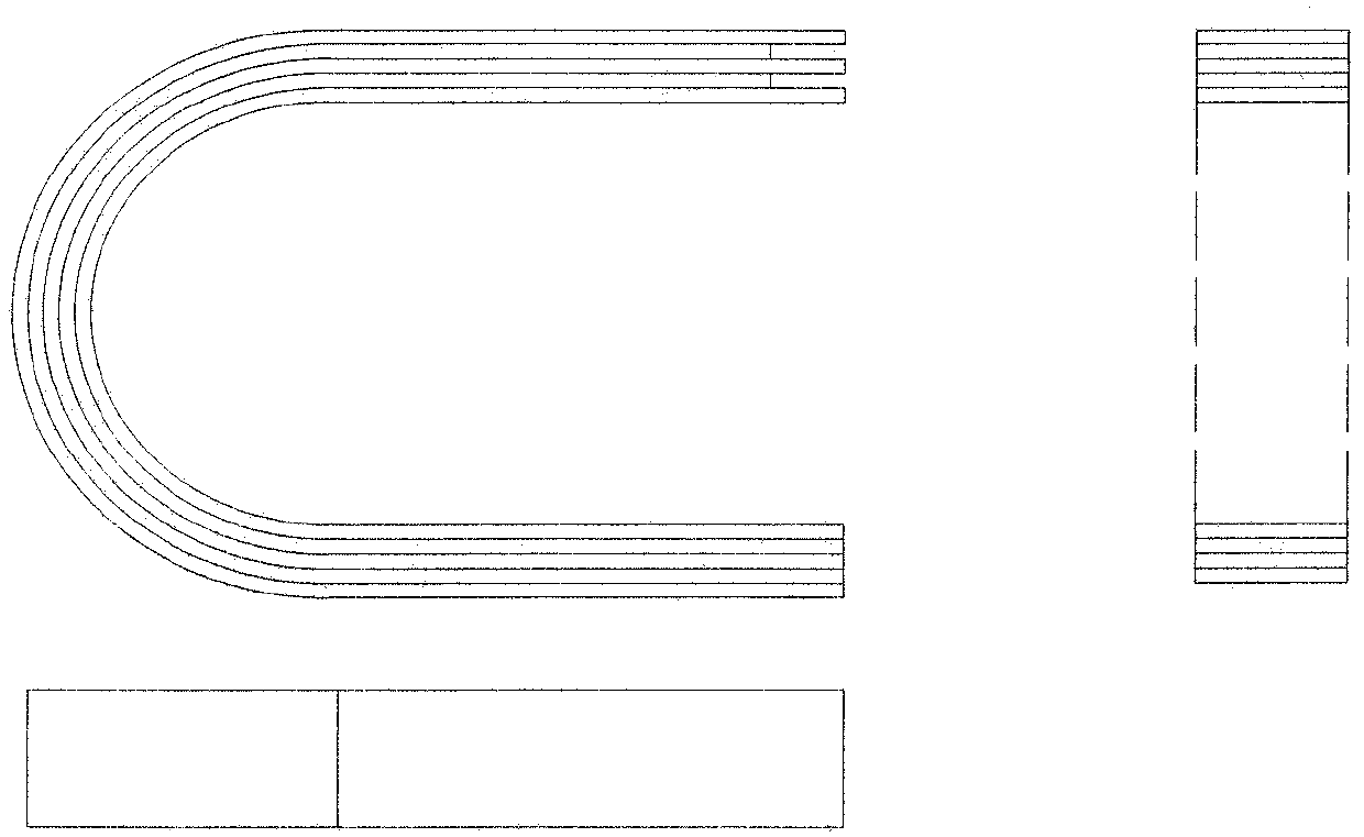
[0027] Example 2, installed on the outside of the entire building:

[0028] Such as figure 2 As shown, when the space of the seismic isolation layer is limited, the laminated U-shaped steel plate bidirectional limiting mechanism can be installed on the outside of the entire building. The board (5) is pre-embedded on the foundation outside the building. Other connections are the same as example 1.


PUM


Abstract

A bidirectional limit mechanism of laminated U-shaped steel plates, belonging to the field of anti-seismic, shock-absorbing and wind-resistant technologies for engineering structures, comprising laminated U-shaped steel plates (1), U-shaped steel plate fixing plates (5), push-pull plates (3), Push-pull groove (6) etc. The push-pull groove (6) is fixed on the upper structure of the shock-isolation layer, and the laminated U-shaped steel plate (1) goes deep into the inside of the push-pull groove, so that the push-pull plate (3) is in the middle of the push-pull groove (6). There is a certain distance between the push-pull plate (3) and the left and right ends of the push-pull groove (6). When the shock-isolation bearing undergoes large deformation, the limiter can limit the deformation of the shock-isolation layer in two directions of push and pull, and play a role in protecting the shock-isolation facilities.

Description

technical field [0001] The invention relates to a position-limiting mechanism of a shock-isolation structure, which belongs to the field of engineering structure shock absorption and shock-isolation technology, and is mainly used for reducing the deformation of a shock-isolation layer under a large earthquake. Background technique [0002] The seismic isolation device has the function of prolonging the natural vibration period of the building structure, avoiding the excellent period of the earthquake, and reducing the seismic response of the building structure to a large extent. However, for near-fault earthquakes and other seismic waves rich in long-period pulses, it is easy to cause large deformations in the isolation layer, causing discomfort to people inside the building, and even causing structural instability or damage to the isolation support. [0003] For such problems, a buffer limit device can be added as a second line of defense. The limit device can be divided i...

Claims


Application Information

Patent Timeline
Patent Type & Authority Patents(China)
IPC IPC(8): E04B1/98
Inventor 杜红凯韩淼冯红达段言彪
Owner BEIJING UNIV OF CIVIL ENG & ARCHITECTURE
Why Eureka
Try Eureka