Dual-power one-stage molding wall grooving machine

A dual-power, slotting machine technology, applied in construction, building construction, etc., can solve the problems of increased operator load, increased slotting process, poor power, etc., to ensure consistency, strong cutting power, and reduce load Effect

Inactive Publication Date: 2015-12-23
ZHEJIANG KWSM ELECTRICAL CO LTD
View PDF0 Cites 2 Cited by
  • Summary
  • Abstract
  • Description
  • Claims
  • Application Information

AI Technical Summary

Problems solved by technology

But there are the following deficiencies in the process of use: 1. Most of the existing hand-held slotting machines adopt the power structure of a single motor. Due to the needs of slotting, one end of the cutter shaft is usually engaged with the motor shaft transmission, so If there is a blade at the end away from the motor shaft, the power is slightly poor, and the blade on the entire cutter shaft cannot output strong cutting torque; 2. The cutter shaft of the slotting machine is an integral structure, and the two ends are set in the casing. Bearings are installed on the main shaft, and slotting saws are installed on both sides. Once there is a problem with this structure, it needs to be repaired or replaced, and the main shaft can only be disassembled from the casing as a whole, which brings a lot of inconvenience to the operator. Time-consuming and labor-intensive, although there are segmented cutter shafts, the blades cannot be flexibly adjusted according to the needs when installing the blades. When the distance between the blades is unreasonable, two lines will be formed on the wall. Parallel and independent channels, and the raised part in the middle needs to be

Method used


Image

  • Dual-power one-stage molding wall grooving machine
  • Dual-power one-stage molding wall grooving machine
  • Dual-power one-stage molding wall grooving machine

Examples


Embodiment Construction

[0025] In order to further understand the present invention, the present invention will be further described below with reference to the accompanying drawings and specific embodiments.

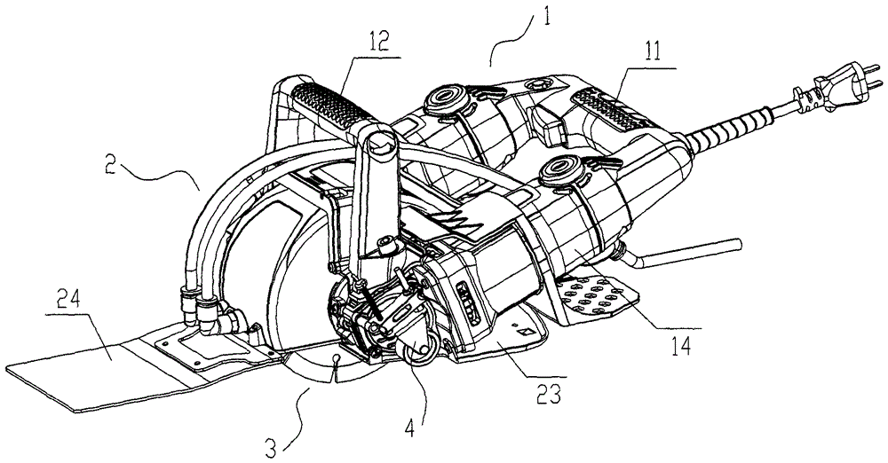
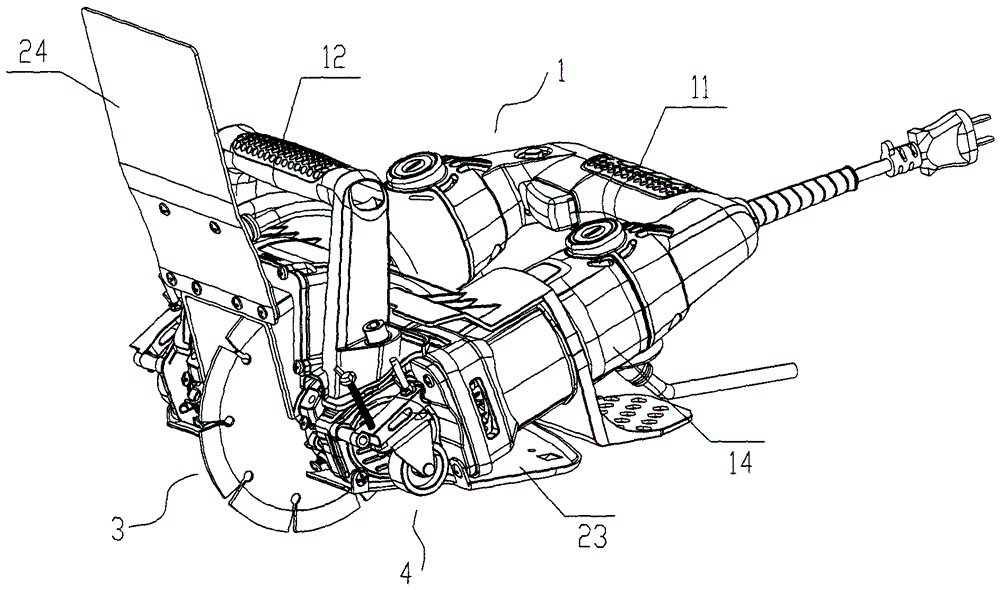
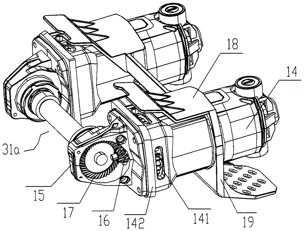
[0026] Such as Figure 1 to Figure 9 As shown, a wall slotting machine with dual power and one-time molding includes two motor covers 14 that are side by side and spaced apart. The motor cover 14 is provided with a motor 13, and the tail of the motor cover 14 passes through a horizontal handle 11 in the horizontal direction. connect. The front end of motor cover 14 is provided with front cover 142, and front cover 142 is provided with axle seat 15, is provided with the cutting assembly 3 that is made of cutter shaft 31a and blade 33 between left and right axle seats 15, the motor shafts of left and right two motors 13 respectively Engaged with the two ends of the cutter shaft 31a, the upper ends of the left and right shaft seats 15 are connected by the vertical handle 12 in the vertical direc...


PUM


Abstract

The invention discloses a dual-power one-stage molding wall grooving machine which comprises two motor covers, wherein the two motor covers are parallel left and right and spaced, and a motor is arranged in each motor cover; the tails of the motor covers are connected through horizontal grips, a front cover is arranged at the front end of each motor cover, and a shaft seat is arranged on the front cover. The two ends of a cutter shaft are rotationally arranged on the left and right shaft seats respectively, and the upper ends of the left and right shaft seats are connected through vertical grips. A dead-corner-free waterproof structure is arranged on the front cover of each motor cover, and the upper half of each blade on the cutter shaft is positioned in the dead-corner-free waterproof structure. When the dual-power one-stage molding wall grooving machine grooves a non-planar wall, the dead-corner-free waterproof structures can be adjusted, so that the front end part of each blade is exposed out to groove the wall on the vertical direction. Groove depth adjustment mechanisms are fixedly arranged on the outer sides of the left and right shaft seats. The dual-power one-stage molding wall grooving machine can stably and powerfully output power to the two ends of the cutter shaft, so that the cutting strength of all blades on the cutter shaft keeps consistent. The adaptability to the grooving terrain is wide, the grooving depth can be flexibly adjusted, and the hand-holding pressure of the grooving machine is reduced.

Description

technical field [0001] The invention relates to the field of wall slotting machines, in particular to a dual-power one-time forming wall slotting machine. Background technique [0002] At present, in the process of office and home interior decoration, circuit wiring, water and gas pipeline laying, TV and communication line wiring are required. Generally, wall slotting machines are used to slot on the ground or walls. The slotting efficiency is high, and its working efficiency is several times or even ten times that of manual slotting, so it is very popular among users. But there are the following deficiencies in the process of use: 1. Most of the existing hand-held slotting machines adopt the power structure of a single motor. Due to the needs of slotting, one end of the cutter shaft is usually engaged with the motor shaft transmission, so If there is a blade at the end away from the motor shaft, the power is slightly poor, and the blade on the entire cutter shaft cannot ou...

Claims


Application Information

Patent Timeline
IPC IPC(8): E04F21/00
Inventor 胡春草宋建中曹长理
Owner ZHEJIANG KWSM ELECTRICAL CO LTD
Why Eureka
Try Eureka