Constant power adjusting system for duplex axial plunger pump and application of constant power adjusting system
A technology for regulating systems and plunger pumps, applied in pump control, liquid variable displacement machinery, machines/engines, etc., can solve the problems of reduced system stability, increased design difficulty and cost of variable mechanisms, etc., to improve service life, Avoid working in an overloaded state, the effect of a high degree of fitting
- Summary
- Abstract
- Description
- Claims
- Application Information
AI Technical Summary
Problems solved by technology
Method used
Image
Examples
Embodiment 1
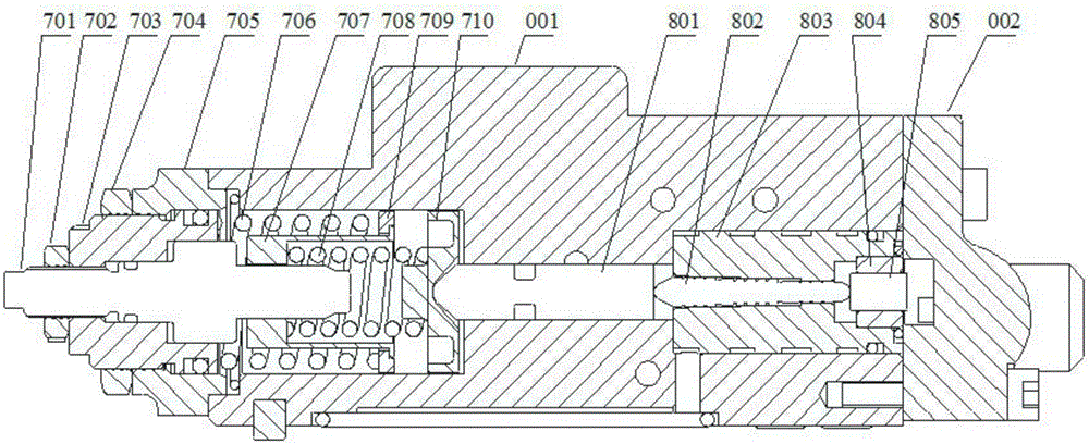
[0044] This embodiment provides a double-connected axial piston pump constant power regulation system, the constant power regulation system is a constant power regulation system in the regulator on the plunger pump, and its specific structure is as follows image 3 As shown, the main valve body 001 is mainly composed of a spring force compensation mechanism 7 and a hydraulic pressure compensation mechanism 8, wherein the spring force compensation mechanism 7 is composed of an inner spring adjustment screw 701, an inner spring adjustment nut 702, an outer spring adjustment screw 703, Outer spring adjusting nut 704, spring side cover 705, outer spring 706, inner spring converter 707, inner spring 708, outer spring converter 709, spring seat 710 and sealing ring and other accessories constitute. The hydraulic pressure compensation mechanism 8 is composed of compensation rod 801, compensation valve core 802, compensation valve sleeve 803, compensation plug 804, compensation piston ...
Embodiment 2
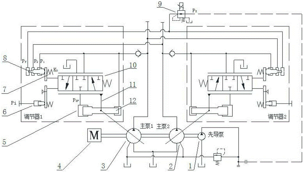
[0056] This embodiment provides a regulator used on a double-connected axial piston pump, the regulator includes the double-connected axial piston pump constant power adjustment system described in Embodiment 1 (by the spring force compensation mechanism 7, the hydraulic pressure Compensation mechanism 8), a negative flow feedback adjustment system (composed of negative flow feedback cylinder 6) and a set of valve control cylinder position follower system (mainly composed of differential cylinder 5, servo valve 10, feedback rod 11, servo plunger 12 composition). The negative flow feedback oil cylinder 6 is connected with the servo valve 10 in the valve control cylinder position follower system, and is used to control the spool movement of the servo valve 10. The constant power adjustment system communicates with the valve control cylinder through the compensation rod 801 of its hydraulic compensation mechanism 8. The servo valve 10 in the position follower system is connected,...
Embodiment 3
[0058] This embodiment provides a double-connected axial piston pump, the structure of which is as follows figure 2 Shown, it comprises pilot pump 1, main pump (front pump 3 and back pump 2), electromagnetic proportional pressure reducing valve 9, each installs a regulator as described in embodiment 2 on front pump 3 and back pump 2.
[0059] In the actual hydraulic power system, the double-connected axial piston pump is usually connected with the prime mover. In this embodiment, the prime mover is selected as a diesel engine, and the prime mover 4 drives two series-connected plunger through-shaft rear pumps 2 through the input shaft. , the front pump 3 and the pilot pump 1 installed at the rear, wherein the plunger pump provides high-pressure power oil for the working actuators, and the pilot gear pump provides high-pressure oil for the control oil circuit. The front pump 3 and the rear pump 2 are respectively equipped with the regulator 1 and the regulator 2 as described in...
PUM
 Abstract
Description
Claims
Application Information
 - R&D
- Intellectual Property
- Life Sciences
- Materials
- Tech Scout
- Unparalleled Data Quality
- Higher Quality Content
- 60% Fewer Hallucinations
Browse by: Latest US Patents, China's latest patents, Technical Efficacy Thesaurus, Application Domain, Technology Topic, Popular Technical Reports.
© 2025 PatSnap. All rights reserved.Legal|Privacy policy|Modern Slavery Act Transparency Statement|Sitemap|About US| Contact US: help@patsnap.com


