Hydraulic system for rapid pressure relief of movable shears

A hydraulic system and pressure relief technology, which is applied in the field of fast pressure relief hydraulic systems for mobile shears, can solve problems affecting the stability of the shearing machine, reduce work efficiency, and slow pressure relief speed, and achieve simple structure, improve work efficiency, and reduce impact small effect

Inactive Publication Date: 2015-12-23
JIANGSU YAWEI MACHINE TOOL
View PDF0 Cites 2 Cited by
  • Summary
  • Abstract
  • Description
  • Claims
  • Application Information

AI Technical Summary

Problems solved by technology

[0002] The shearing action of the shearing machine is to realize the shearing action through the oil supply and oil return of the oil cylinder to make the tool holder rise or fall. When the traditional hydraulic system releases pressure, the pressure release speed is slow, which reduces the work efficiency. In the middle, due to the large impact of the tool post, it will generate a lot of noise, which affects the stability of the entire shearing machine

Method used


Image

  • Hydraulic system for rapid pressure relief of movable shears

Examples


Embodiment Construction

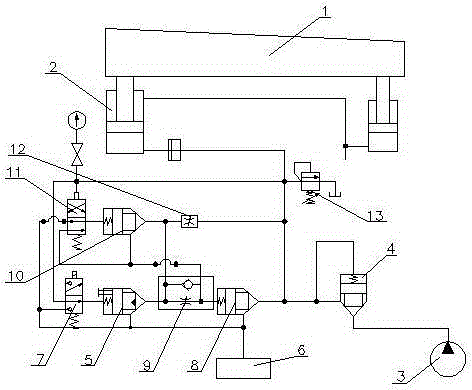
[0013] A quick pressure relief hydraulic system for mobile shears, comprising an oil cylinder 2 installed at the lower end of a tool holder 1, the oil cylinder 2 is connected to an oil supply pump 3 through a pipeline, and a hydraulic control check valve 4 is provided on the pipeline. The pipeline between the hydraulic control check valve 4 and the oil cylinder 2 is provided with a first oil return line and a second oil return line respectively connected to the plug-in throttle valve 5, and the plug-in throttle valve 5 is connected to the oil return tank 6 connected, the plug-in throttle valve 5 is connected with an electromagnetic ball valve 7, a check valve 8 is provided on the second oil return pipeline, and a one-way valve 8 is provided between the check valve 8 and the plug-in throttle valve 5. Throttle valve 9, the first oil return pipeline is directly connected to the oil return tank 6 through an oil circuit, a cartridge valve 10 is provided on the oil circuit, and the c...


PUM


Abstract

The invention relates to a hydraulic system for rapid pressure relief of movable shears. The hydraulic system comprises oil cylinders which are installed at the lower end of a knife rest. The oil cylinders are connected with an oil supply pump through a pipeline. A hydraulic-control one-way valve is arranged on the pipeline. A first oil return pipeline and a second oil return pipeline are arranged on the portion, between the hydraulic-control one-way valve and the oil cylinders, of the pipeline and both connected with a cartridge throttling valve. The cartridge throttling valve is connected with an oil return tank and an electromagnetic ball valve. A one-way valve is arranged on the second oil return pipeline. A one-way throttling valve is arranged between the one-way valve and the cartridge throttling valve. The first oil return pipeline is directly connected with the oil return tank through an oil circuit. A cartridge valve is arranged on the oil circuit and connected with a pressure valve. The pressure valve is connected with the oil cylinders through pipelines. The hydraulic system is simple in structure, hydraulic oil in the oil cylinders can flow back into the oil tank rapidly, working efficiency is improved, impact is small, and noise is low.

Description

technical field [0001] The invention relates to a hydraulic system for rapid pressure relief of mobile shears. Background technique [0002] The shearing action of the shearing machine is to realize the shearing action through the oil supply and oil return of the oil cylinder to make the tool holder rise or fall. When the traditional hydraulic system releases pressure, the pressure release speed is slow, which reduces the work efficiency. In the process, due to the large impact of the tool post, it will generate a lot of noise, which affects the stability of the entire shearing machine. Contents of the invention [0003] In view of the above-mentioned defects, the object of the present invention is to provide a rapid pressure relief hydraulic system for mobile shears, which improves working efficiency, has small impact and low noise. [0004] The technical scheme that the present invention adopts for this reason is: [0005] It includes an oil cylinder installed at the l...

Claims


Application Information

Patent Timeline
Patent Type & Authority Applications(China)
IPC IPC(8): F15B11/04F15B11/08
Inventor 潘恩海杨建军朱蔚盛川野杨彬
Owner JIANGSU YAWEI MACHINE TOOL
Why Eureka
Try Eureka