Guide rail assembly, guide rail and robot moving device

A mobile device and robot technology, applied in the transmission device, friction transmission device, manipulator and other directions, can solve the problems such as the accuracy and easy deformation affecting the robot picking and placing workpieces, and achieve high production quality, stability and overall strength. Effect

Active Publication Date: 2015-12-23
JIANGXI JUST NUMERICAL CONTROL TECH
View PDF6 Cites 9 Cited by
  • Summary
  • Abstract
  • Description
  • Claims
  • Application Information

AI Technical Summary

Problems solved by technology

[0004] The purpose of the present invention is to overcome the deficiencies of the prior art, adapt to the actual needs, and provide a guide rail assembly, guide rail, and robot moving device to solve the technical problem that the current guide rail assembly is easily deformed during use, thereby affecting the accuracy of the robot for picking and placing workpieces

Method used


Image

  • Guide rail assembly, guide rail and robot moving device
  • Guide rail assembly, guide rail and robot moving device
  • Guide rail assembly, guide rail and robot moving device

Examples


Embodiment 1

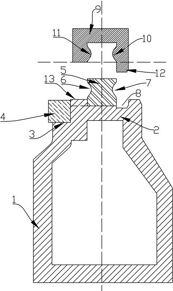
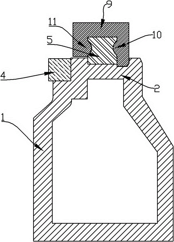
[0030] Embodiment 1: a kind of rail assembly, refer to figure 1 , figure 2 Including a base 1, a support plate 2 arranged on the upper end of the base 1; in this design, a linear guide rail belt 5 is also fixed on the support plate 2, and the linear guide rail belt 5 is arranged along the length direction of the base, and Inwardly recessed groove bands 6, 7 are respectively arranged in the middle part of the left and right side walls of the linear guide band 5, and the groove surfaces of the grooves in the groove bands 6, 7 are arc surfaces; this guide rail assembly It also includes a slider 9 whose end surface is in the shape of a "[" and is set upside down. On the inner walls of both sides of the slider 9, protrusions 10 matching the grooves on the groove belt are respectively provided. 11. The slider 9 is buckled on the linear guide rail belt 5, and the two protrusions 11 and 10 on the slider 9 are engaged with the groove belts 6 and 10 on both sides of the linear guide r...

Embodiment 2

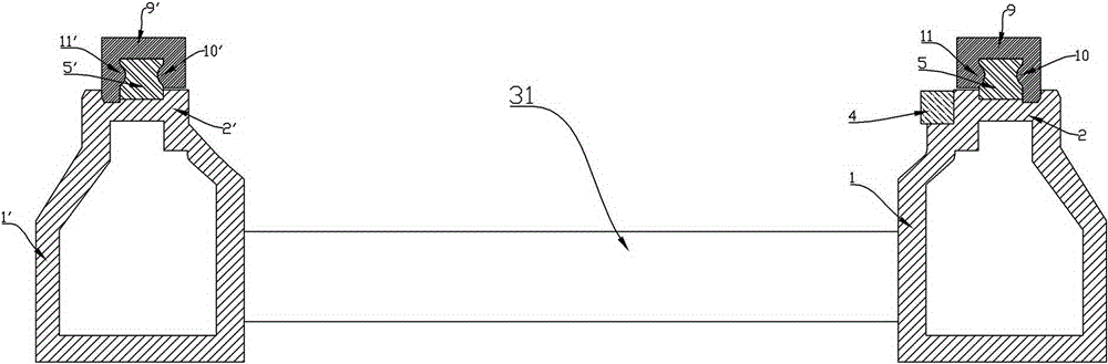
[0032] Embodiment 2: a kind of guide rail, refer to image 3 , Figure 4 The same place as Embodiment 1 will not be repeated, and the difference is that the designed guide rail of the present invention comprises two guide rail assemblies as described in Embodiment 1; the two guide rail assemblies A, B are arranged in parallel, And between the two guide rail assemblies A and B, a connecting piece connecting the two guide rail assemblies together is provided. Described connector it comprises a plurality of transverse connecting rods 31, 32, 33 and a vertical connecting rod 34, a plurality of transverse connecting rods are equidistantly arranged in parallel between the two guide rail assemblies A, B, and the transverse connecting rods The two ends are respectively fixedly connected to the bases of the guide rail assemblies on both sides, and the vertical connecting rod 34 is arranged in the middle of a plurality of horizontal connecting rods, and is vertically arranged with the ...

Embodiment 3

[0033] Embodiment 3: a kind of robot mobile device, see Figure 1 to Figure 5 The same place as Embodiment 2 will not be repeated, and the difference is that the robot mobile device designed by the present invention includes a robot 21, a guide rail as described in Embodiment 2, and the base below the robot is fixed on two guide rails on the two slides above the assembly.

[0034] Further, the device further includes a moving plate 22, on which the robot 21 is arranged, and the moving plate 22 is fixed on the two sliding pieces 9, 9' above the two guide rail assemblies. Further, this design is on one side of the support plate 2 ( figure 1 The base 1 on the left side) is also provided with a linear step 3 arranged along the length direction of the base, and a toothed belt 4 is also provided on the linear step, and further, it is fixed under the moving plate There is a power motor (not shown in the figure), and a power gear is arranged on the output shaft of the power motor, t...


PUM


Abstract

The invention relates to a guide rail assembly, a guide rail and a robot moving device. By means of the guide rail assembly, the guide rail and the robot moving device, the technical problem that an existing guide rail assembly is liable to deformation in use is solved. The guide rail assembly comprises a base and a support plate arranged at the upper end of the base. A linear guide rail belt is further fixed to the support plate. The linear guide rail belt is arranged in the length direction of the base, and the middles of the left side wall and the right side wall of the linear guide rail belt are each provided with an inward-concave groove zone. The guide rail assembly further comprises a sliding part arranged in an upside down mode. The end face of the sliding part is of a [-shaped structure. The inner walls of the two sides of the sliding part are provided with protrusions respectively, and the protrusions are matched with grooves in the groove zones. The sliding part is placed on the linear guide rail belt in an upside down mode, and the two protrusions on the sliding part are clamped in the groove zones on the two sides of the linear guide rail belt respectively. The guide rail is composed of two guide rail assemblies. The robot moving device comprises a robot and the guide rail. A base under the robot is fixed to two sliding parts on two guide rail assemblies.

Description

technical field [0001] The invention relates to the technical field of flexible production lines, in particular to a guide rail assembly, a guide rail, and a robot moving device. Background technique [0002] The gradual disappearance of the demographic dividend has led to the continuous rise of manpower and manufacturing costs of enterprises. Therefore, it is the demand of large, medium and small enterprises to improve the flexibility of production, improve the efficiency of machine tool use and reduce the labor intensity of operators. The flexible automated production line is based on multiple (types) of CNC machine tools or machining centers, which are connected by robots or automated logistics systems, and are uniformly controlled and managed by the main control computer and related software to form unmanned automated manufacturing of various products. system. [0003] In the context of the continuous improvement of the reliability of robots and the continuous reduction...

Claims


Application Information

Patent Timeline
Patent Type & Authority Applications(China)
IPC IPC(8): F16C29/02F16H19/04B25J5/02
Inventor 刘华吴靓戴琳叶寒陶志鹏郑德新阮子宏江涛张军
Owner JIANGXI JUST NUMERICAL CONTROL TECH
Why Eureka
Try Eureka