Air conditioner device
A technology for air-conditioning equipment and air-conditioning internal units, applied in air-conditioning systems, lighting and heating equipment, space heating and ventilation, etc., which can solve problems such as high preparation costs and use costs, increased energy consumption, and complex air-conditioning structures, and achieve structural Simplicity, heat load reduction, and low energy consumption
- Summary
- Abstract
- Description
- Claims
- Application Information
AI Technical Summary
Problems solved by technology
Method used
Image
Examples
Embodiment 1
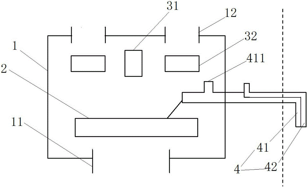
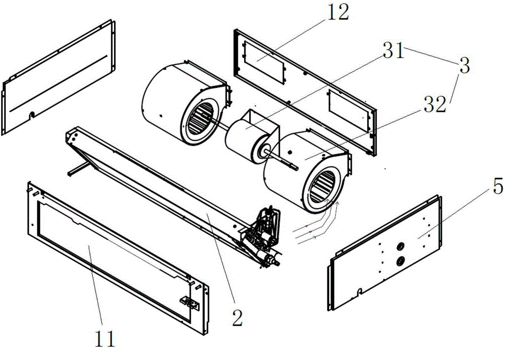
[0035] Such as figure 1 , figure 2 As shown, an air conditioner proposed in this embodiment includes: a housing 1, a heat exchanger 2, a first pipeline 4 (such as figure 1 shown) and fan system 3. Wherein, the housing 1 is provided with an air outlet 12 and an air return 11 . The heat exchanger 2 is arranged in the casing 1 and is used for performing heat exchange treatment on the return air entering the casing 1 . The first pipe 4 is used to connect the inside of the casing 1 with the outside, one end of which is placed inside the casing 1, and the other end is placed outside. The fan system 3 is arranged in the casing 1, and is used to make outdoor fresh air enter the casing 1 through the first pipe 4, and deliver the fresh air and return air entering the casing 1 to the room through the air outlet 12 of the casing 1. .
[0036] When the air conditioner provided by this embodiment is in use, the fan system will generate suction force to the fresh air inlet of the first...
Embodiment 2
[0042] Such as figure 1 As shown, this embodiment provides an air conditioner. Compared with the previous embodiment, the first pipe 4 in this embodiment is a condensed water pipe. The condensate pipe is used to discharge the condensate on the heat exchanger to the outside.
[0043] Preferably, the air conditioner internal unit further includes a condensed water collection tank connected to the heat exchanger 2 for collecting condensed water on the heat exchanger 2 . The port at one end of the condensed water pipe located in the casing 1 is connected to the condensed water collection tank for discharging the condensed water to the outside. The condensed water pipe is provided with a fresh air inlet 411 at a position close to the air inlet of the fan system 3 and away from the heat exchanger 2 . This setting can prevent the fresh air from being dehumidified when passing through the heat exchanger (evaporator).
[0044] When the air conditioner in this embodiment is in use, d...
Embodiment 3
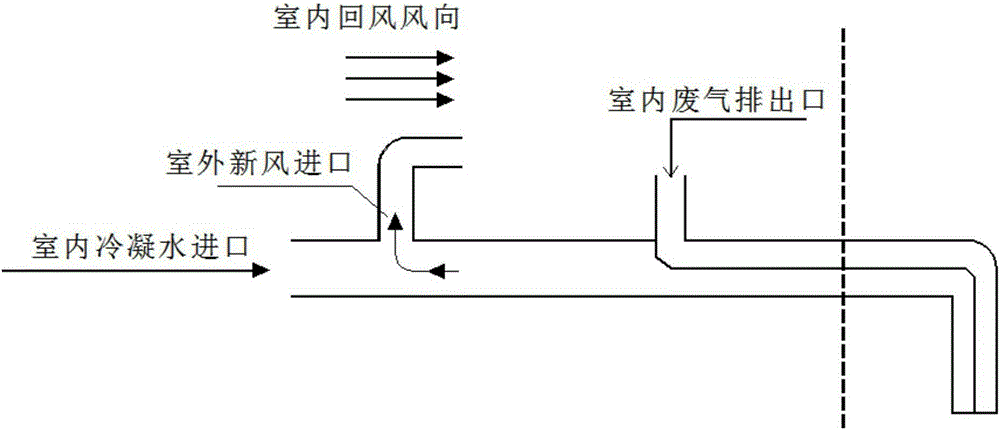
[0046]This embodiment provides an air conditioner. On the basis of the above embodiments, the inventor of the present invention considered that the outdoor air continuously flows into the room to form a positive pressure in the room. If the user stays indoors for a long time, he will feel uncomfortable. , and the discharge of indoor dirty air will improve the cleanliness of the air. Therefore, the air conditioner in this embodiment also includes a second pipeline, the second pipeline is placed outside the casing, and one end of the second pipeline is set indoors, and the other end is set outdoors, due to the positive pressure in the room, the pressure of the indoor and outdoor air is used to Poor, so that the dirty air in the room is discharged to the outside through the second pipe.
[0047] figure 1 and image 3 The dotted line in represents the dividing line between indoor and outdoor, preferably, such as figure 1 and image 3 As shown, the condensed water pipe has a fi...
PUM
 Abstract
Description
Claims
Application Information
 - R&D
- Intellectual Property
- Life Sciences
- Materials
- Tech Scout
- Unparalleled Data Quality
- Higher Quality Content
- 60% Fewer Hallucinations
Browse by: Latest US Patents, China's latest patents, Technical Efficacy Thesaurus, Application Domain, Technology Topic, Popular Technical Reports.
© 2025 PatSnap. All rights reserved.Legal|Privacy policy|Modern Slavery Act Transparency Statement|Sitemap|About US| Contact US: help@patsnap.com


