Oil wear debris monitoring sensor with vibration signal output characteristic and on-line oil monitoring system

A technology for monitoring sensors and oil abrasive particles, applied in vibration testing, testing of machine/structural components, instruments, etc., can solve the problems that microprocessors are not competent for sensor signal acquisition, processing and analysis, and sensors are difficult to configure on-line monitoring, etc. To achieve the effect of small size

Active Publication Date: 2015-12-23
GUILIN UNIV OF ELECTRONIC TECH
View PDF12 Cites 4 Cited by
  • Summary
  • Abstract
  • Description
  • Claims
  • Application Information

AI Technical Summary

Problems solved by technology

However, the existing online oil wear particle sensors must use DAQ cards to collect data and use traditional computers for analysis. The existing microprocessors are not competent for the acquisition, processing and analysis of such sensor signals.
Therefore, such sensors are difficult to configure and realize online monitoring in mobile mechanical equipment (such as automobile engines)

Method used


Image

  • Oil wear debris monitoring sensor with vibration signal output characteristic and on-line oil monitoring system
  • Oil wear debris monitoring sensor with vibration signal output characteristic and on-line oil monitoring system

Examples


Embodiment Construction

[0024] Embodiments of the present invention will be described in further detail below in conjunction with the accompanying drawings.

[0025] Embodiment of Oil Wear Particle Monitoring Sensor Outputting Vibration Signal

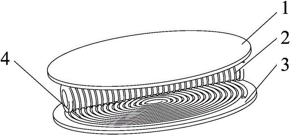
[0026] In this example, the oil wear particle monitoring sensor that outputs vibration signals, such as figure 1 As shown, it includes an upper planar coil 1 and a lower planar coil 3 parallel to each other. The two planar coils 1 and 3 are the same, and both are planar spiral coils wound clockwise with single-layer wiring, and the upper planar coil 1 is connected to the lower planar coil 3. The upper projection overlaps with the lower planar coil 3; the distance between the two planar coils 1 and 3 in this example is 18mm. The planar coils 1 and 3 have an inner diameter of 4 mm, a wire diameter of 0.3 mm, and a wire distance of 0.3 mm, with a total of 15 turns. The two planar coils 1, 3 are connected in parallel with the same constant current source excita...


PUM

PropertyMeasurementUnit
distanceaaaaaaaaaa

Abstract

The invention provides an oil wear debris monitoring sensor with a vibration signal output characteristic and an on-line oil monitoring system. An induction coil of the monitoring sensor is located between two overlapped and parallel plane coils which are connected with a constant-current source, wherein the axis of the induction coil is parallel to the plane coils, and gaps are formed between the induction coil and the plane coils; the length of the induction coil is smaller than the outer diameter of each plane coil. The sensor of the on-line oil monitoring system is mounted in a lubrication circuit of a mechanical device, an output of the induction coil of the sensor is connected to a Maxwell-Wien bridge, outputs of the Maxwell-Wien bridge are connected with an oil wear debris signal acquisition circuit and a vibration signal acquisition circuit respectively and then connected to a microcontroller via an analog-digital conversion circuit; a comprehensive fault analysis module is arranged in the microcontroller which is connected with a display screen, metal wear debris signals and vibration signals are displayed on line, and the current fault information of the mechanical device is displayed. The mechanical fault can be judged timely and accurately, and the system is small in size and portable and can be mounted to a mobile device for on-line fault monitoring.

Description

technical field [0001] The invention relates to the field of machine state monitoring and fault diagnosis, in particular to an oil abrasive particle monitoring sensor outputting vibration signals and an oil online monitoring system. Background technique [0002] With the continuous development of mechanical equipment technology, its internal structure is also more complex. Correspondingly, the means of monitoring the operation status of mechanical equipment are also constantly improving, so as to continuously maintain the normal operation of mechanical equipment. The most commonly used monitoring signals for mechanical operation status are three types of vibration signals: displacement, velocity and acceleration. This kind of vibration signal can accurately characterize the dynamic characteristics of equipment in real time, from which early weak fault signals can be extracted and fault location can be performed. [0003] In order to predict early failures more effectively,...

Claims


Application Information

Patent Timeline
Patent Type & Authority Applications(China)
IPC IPC(8): G01N15/00G01M7/02G01M15/05G01M99/00
Inventor 王衍学丁永彬何水龙蒋占四
Owner GUILIN UNIV OF ELECTRONIC TECH
Why Eureka
Try Eureka