Device and method for fiber and pitch adhesion testing

A technology for testing devices and testing methods, which is applied in the direction of measuring devices, mechanical devices, instruments, etc., can solve problems such as shortages, and achieve the effects of simple operation, accurate test results, and easy production and operation

Active Publication Date: 2015-12-23
YANGZHOU UNIV
View PDF8 Cites 11 Cited by
  • Summary
  • Abstract
  • Description
  • Claims
  • Application Information

AI Technical Summary

Problems solved by technology

[0004] Aiming at the current technical problem of lacking relevant test devices and methods to characterize the adhesion performance of fib...

Method used


Image

  • Device and method for fiber and pitch adhesion testing
  • Device and method for fiber and pitch adhesion testing
  • Device and method for fiber and pitch adhesion testing

Examples


Embodiment 1

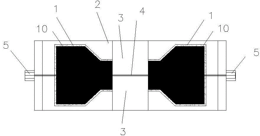
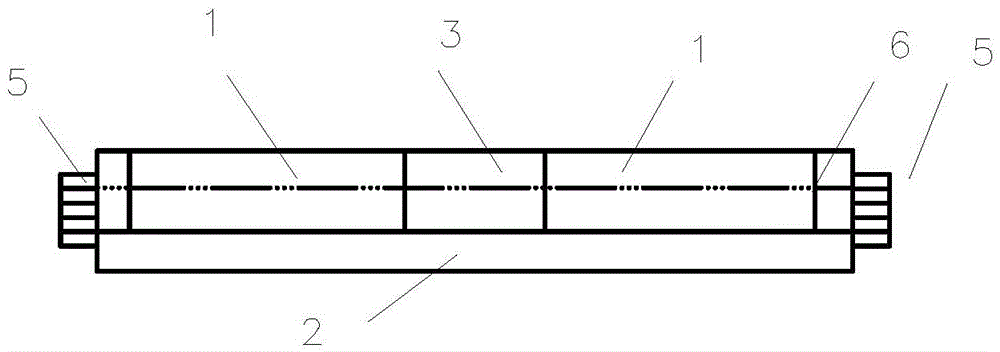
[0029] The fibrous asphalt adhesion performance testing device adopted in the present embodiment 1 comprises asphalt pouring groove 1, test form bottom plate 2, metal clip 3, fiber caulking 4 and bolt 5 (see figure 1 ), two pitch filling grooves 1 with a length of 6 cm are an axisymmetric octagonal notch container member with a bottom plate and an open side wall, and form a closed groove with the metal clamp block 3 at the end of the open side wall, the The side wall of the opening is located on the vertical plane of the centerline of the axis of the container member. The width of the asphalt pouring groove 1 is narrowed at the end of the opening side wall. On both sides of the metal clamp block 3, the total length of the three is about 19cm. The fiber caulking 4 is the groove at the intersection of the three and the axis centerline of the test device, and its depth is half the height of the asphalt pouring groove 1 (see Figure 4 ) with a width of 3mm. The fiber caulking 4 ...

Embodiment 2

[0037] The fibrous asphalt adhesion performance testing device adopted in the present embodiment 2 comprises asphalt pouring groove 1, test mold bottom plate 2, metal clip 3, fiber caulking 4 and bolt 5 (see Figure 5 ). The asphalt pouring groove 1 is an axisymmetric octagonal notch container member with a bottom plate and an open side wall with a length of 6 cm, and forms a closed groove with the metal clamp block 3 positioned at the end of the open side wall, and the open side wall Located on the vertical plane of the center line of the container member axis, the width of the asphalt pouring groove 1 is narrowed at the end of its opening side wall, the asphalt pouring groove 1 is detachably placed on the bottom plate 2 of the trial mold, and the fiber caulking 4 is the asphalt pouring groove 1 The groove of the side wall and the metal clamp block 3 at the intersection with the center line of the shaft, its depth is half of the height of the asphalt pouring groove 1 (see F...


PUM

PropertyMeasurementUnit
Softening pointaaaaaaaaaa

Abstract

The invention provides a device and method for fiber and pitch adhesion testing. The testing device comprises a pitch injection groove, a mold testing base plate, a clamp block, a fiber caulked joint and a fastening device, wherein the pitch injection groove is an axisymmetric polygonal notch container component provided with a base plate and an open side wall, a closed groove is formed by the pitch injection groove and the clamp block located at the open side wall end, the open side wall end becomes narrow and is detachably arranged on the mold testing base plate, the open side wall is located on the vertical plane of the axial central line of the container component, the fiber caulked joint is a groove located at the position where the pitch injection groove and the clamp block intersect with the axial central line of the testing device and penetrates through the whole testing device, and bolts are arranged at the head side and end side of the fiber caulked joint respectively. According to the method, various fibers are bound into a fiber bundle with similar circular section diameters, the mass change of the fiber bundle before and after pitch extrusion at the pitch softening point temperature is calculated so as to test fiber and pitch adhesion in a quantified mode, and then a testing result is more objective and more comparable.

Description

technical field [0001] The invention relates to a material test device and method, in particular to a fiber adhesion performance test device and method in asphalt mortar containing fiber materials, in particular to a fiber and asphalt material adhesion performance test device and method. Background technique [0002] Fiber asphalt mixture is widely used in domestic and foreign projects. The mixture utilizes the reinforcing and toughening effect of the fiber material on the asphalt to enhance the high temperature stability and fatigue resistance of the asphalt mixture. Its anti-high temperature deformation and fatigue cracking performance are closely related to the performance of the fiber itself and the adhesion performance of asphalt. In order to research the fiber asphalt mixture with better performance, it is particularly important to test the fiber adhesion performance. However, there are many kinds of asphalt mixture fibers, and the bonding performance between differe...

Claims


Application Information

Patent Timeline
IPC IPC(8): G01N19/04
Inventor 肖鹏江杰丁燕
Owner YANGZHOU UNIV
Why Eureka
Try Eureka