
The temperature control device of the pressure chamber of the hollow cylinder instrument in frozen soil

A technology of temperature control device and hollow cylinder, which is applied in the direction of using electric method for temperature control, using stable tension/pressure to test the strength of materials, etc. It can achieve the effect of good automatic adjustment, good thermal insulation effect, and satisfying pressure bearing capacity.

Active Publication Date: 2018-03-20
NORTHWEST INST OF ECO ENVIRONMENT & RESOURCES CAS
View PDF8 Cites 0 Cited by
  • Summary
  • Abstract
  • Description
  • Claims
  • Application Information

AI Technical Summary

Problems solved by technology

Since this method does not consider the pressure bearing capacity of the copper tube and the heat exchange between the upper and lower ends of the pressure chamber and the surrounding environment, the copper tube is crushed under high pressure and cannot work, and the temperature uniformity inside the pressure chamber is very poor. (The temperature difference between the top and bottom of the sample is always within ±1 o C or above), and the ambient temperature fluctuates greatly day and night
These design flaws make it impossible to carry out experimental research on the mechanical properties of frozen soil under complex stress path conditions with the existing hollow cylindrical instrument for frozen soil

Method used


Image

  • The temperature control device of the pressure chamber of the hollow cylinder instrument in frozen soil
  • The temperature control device of the pressure chamber of the hollow cylinder instrument in frozen soil
  • The temperature control device of the pressure chamber of the hollow cylinder instrument in frozen soil

Examples


Embodiment Construction

[0023] In conjunction with the accompanying drawings, the present invention is further described in detail through actual measurement examples:

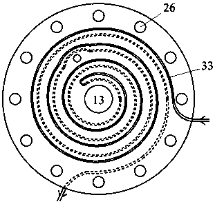
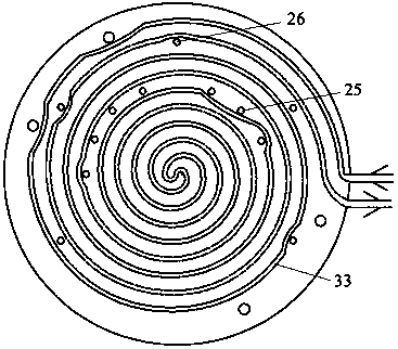
[0024] like Figure 1-6As shown, a temperature control device for the pressure chamber of a hollow cylinder instrument for frozen soil, including a stainless steel pressure chamber 1, a hollow cylindrical sample 2, a temperature sensor 3, an upper pressure head 4, a lower pressure head 5, a plastic adapter 6, and a stainless steel lower base 7. Heat insulation bottom plate 8, inverted U-shaped copper tube 9, pressure heat transfer medium 10, double spiral cold liquid circulation tank 11, insulation layer 12, testing machine dowel 13, cold bath 14, data acquisition system 15, Pressure chamber support rod 16, pore water pressure sensor 17, inner cavity oil injection hole 19, outer cavity oil injection hole 19, permeable stone 20, sealing ring 21, latex film inside and outside the sample 22, ventilating drainage hole 23, connecting plas...


PUM


Abstract

The invention relates to a temperature control system for a hollow cylinder pressure chamber in frozen soil, which is characterized in that a double-helix cooling bath circulation groove is engraved on the wall of the pressure chamber, and the cooling bath circulates in the circulation groove to reduce the temperature of the pressure-bearing heat transfer medium inside the pressure chamber. There is an inverted U-shaped copper tube and a temperature sensor in the inner cavity of the hollow cylindrical sample. The three temperature sensors are distributed on the upper, middle and lower positions of the outer wall of the sample. The data is fed back to the cooling bath controller, and the upper and lower temperature sensors monitor the temperature fluctuations in the corresponding positions. The pressure chamber is equipped with upper and lower cold plates to reduce the heat exchange between the pressurized heat transfer medium in the pressure chamber and the outside world, and adjust the temperature of the pressure chamber through the movement of the cold bath in the cold plate. The invention can rapidly lower the temperature of the sample, ensure that the temperature of the sample is uniform and constant during the whole test period, and is not affected by the temperature change of the external room, and provides a technical guarantee for revealing the mechanical properties of frozen soil under the action of complex stress paths.

Description

technical field [0001] The invention relates to a temperature control device for a pressure chamber of a hollow cylinder instrument for frozen soil, that is, a test device for indoor mechanical parameter testing of frozen soil under complex stress path conditions. Using this device, the cooling and constant temperature process of the hollow cylinder of frozen soil can be realized during the dynamic, static and torsional loading of the hollow cylinder instrument, so that the sample can reach the temperature accuracy required by the mechanical test, and finally ensure the mechanical parameters of the frozen soil. The accuracy of the determination. Background technique [0002] Soil properties are affected by the stress path. Ideally, only the indoor test conditions can completely simulate the real loading process to reflect the real response of the soil, especially under dynamic conditions. The most common dynamic loads in engineering construction in cold regions, such as ear...

Claims


Application Information

Patent Timeline
Patent Type & Authority Patents(China)
IPC IPC(8): G05D23/19G01N3/08
Inventor 王大雁常小晓马巍吴青柏王永涛郭妍雷乐乐赵淑萍穆彦虎
Owner NORTHWEST INST OF ECO ENVIRONMENT & RESOURCES CAS
Learn More