Timer IP (Intellectual Property) core connected with 8-bit microprocessor application system and method thereof for realizing timing control of timer

An application system and microprocessor technology, applied in the direction of machine execution devices, etc., can solve the problems of large circuit scale and heavy maintenance workload

Inactive Publication Date: 2015-12-23
LUSHAN COLLEGE OF GUANGXI UNIV OF SCI & TECH +1
View PDF5 Cites 3 Cited by
  • Summary
  • Abstract
  • Description
  • Claims
  • Application Information

AI Technical Summary

Problems solved by technology

[0006] The third method is to use non-programmable hardware timing, and each timer is realized by an independent hardware circuit; u

Method used


Image

  • Timer IP (Intellectual Property) core connected with 8-bit microprocessor application system and method thereof for realizing timing control of timer
  • Timer IP (Intellectual Property) core connected with 8-bit microprocessor application system and method thereof for realizing timing control of timer
  • Timer IP (Intellectual Property) core connected with 8-bit microprocessor application system and method thereof for realizing timing control of timer

Examples


Embodiment 1

[0174] A timer IP core A that can be set to form six 32-bit timers and connected to an 8-bit microprocessor application system (hereinafter referred to as: timer IP core A):

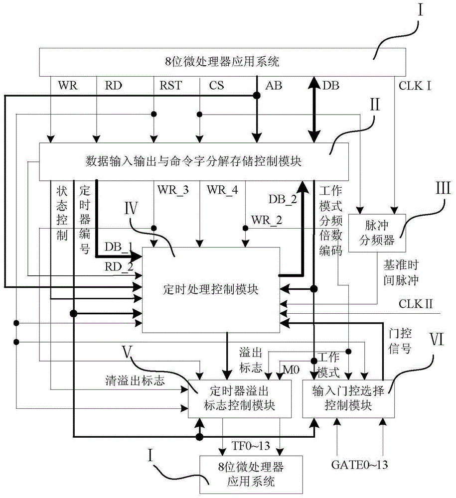
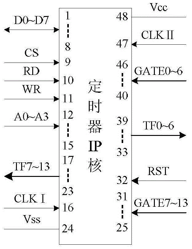
[0175] As mentioned above, the timer IP core A connected with the 8-bit microprocessor application system includes data input and output and command word decomposition storage control module II, pulse 12 frequency divider III, timing processing control module IV, timer overflow flag Control module Ⅴ, input gate selection control module Ⅵ (see figure 1 ), the timer IP core A has 48 pins, its package diagram see figure 2 ;

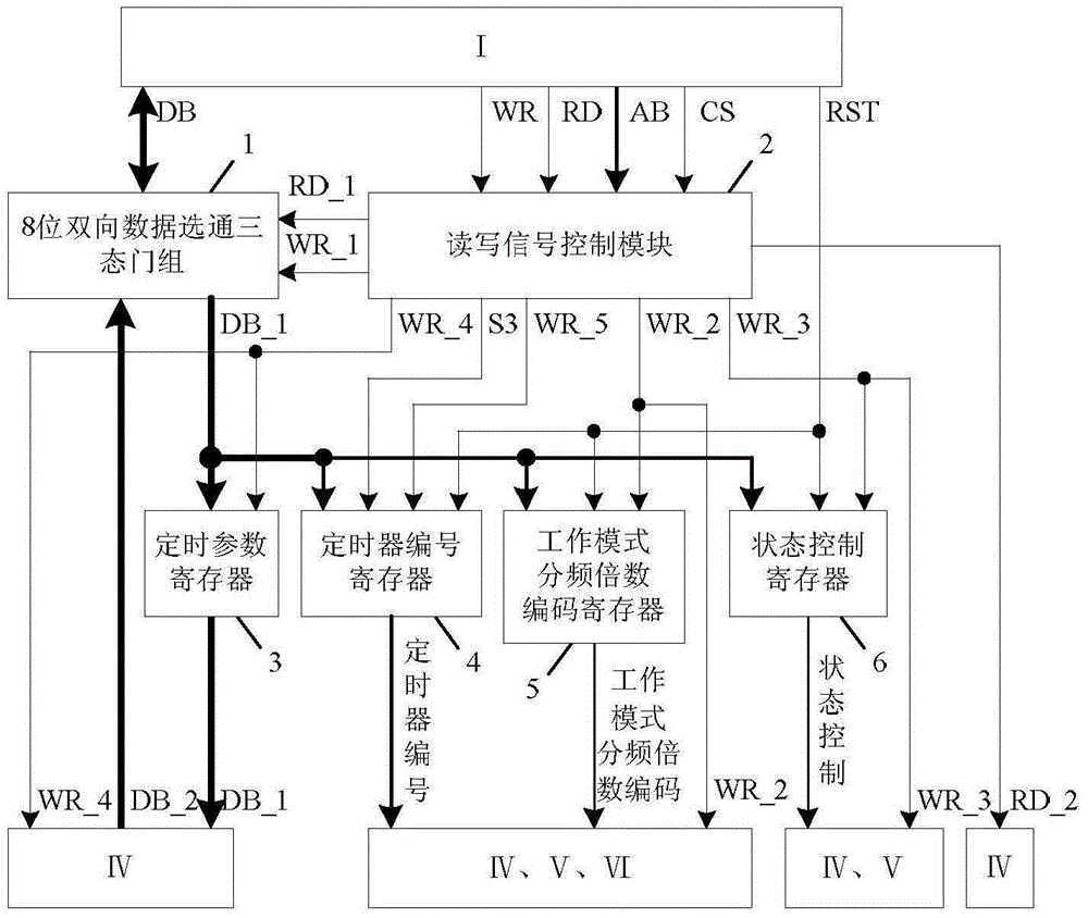
[0176] Such as image 3 As shown, the data input and output and command word decomposition storage control module II includes 8-bit bidirectional data strobe tri-state gate group 1, read and write signal control module 2, timing parameter register 3, timer number register 4, working mode division Frequency multiple encoding register 5, state control register 6;

[0177]The 8-bit b...

Embodiment 2

[0268] A timer IP core B that can be set to form three 32-bit timers and connected to an 8-bit microprocessor application system (hereinafter referred to as: timer IP core B):

[0269] The timer IP core B has 34 pins, the package diagram see Figure 6 ;

[0270] The basic structure of this timer IP core B is the same as embodiment one, and the difference with embodiment one is: this timer IP core B has 7 16-bit timers, and 6 of them can form 3 32-bit timers; The overflow flag output signals TF0~13 of the timer overflow flag control module V are transformed into overflow flag output signals TF0~7, and the gate control input signals GATE0~13 of the input gate selection control module VI are transformed into gate control input signals GATE0 ~7, see figure 1 The connection line of the 4th timer number value S3 and the timer number register 4 of the read-write signal control module 2 of the data input and output and the command word decomposition storage control module II is dele...

Embodiment 3

[0274] A timer IP core connected with an 8-bit microprocessor application system, figure 1 The pulse 12 frequency divider III determines the timing reference clock of the timer IP core, transforms the pulse 12 frequency divider III into a 50 frequency divider III, and adapts to the case where the clock frequency of an 8-bit microprocessor is greater than 12MHz.


PUM


Abstract

The invention discloses a timer IP (Intellectual Property) core connected with an 8-bit microprocessor application system. The timer IP core comprises a data input/output and command word decomposition storage control module, a pulse 12 frequency divider, a timing processing control module, a timer overflow flag control module and an input gating selection control module. An FPGA (Field Programmable Gate Array) is applied to design the timer IP core formed by a hard connection control circuit, the timer IP core is provided with fourteen 16-bit timers, wherein twelve 16-bit timers can form six 32-bit timers, one command word sets a working mode and selects the reference clock frequency division multiple of the timer, and the other command word controls a working state. The program execution time of the 8-bit microprocessor is not occupied except that the 8-bit microprocessor carries out the operations, including function and state setting, timing parameter transmission and current timing value reading, on the timer. Each 16-bit/32-bit timer has a function of automatically reloading the timing parameter, so that timing precision is improved. The requirements of the timing of a plurality of timers and the timing control of a system can be met.

Description

technical field [0001] The present invention relates to a timer IP core connected with an 8-bit microprocessor application system and a method for realizing timer timing control thereof, in particular to a feature based on FPGA parallel processing, which can be combined with FPGA designed hard-wired circuits A timer IP core connected to an 8-bit microprocessor application system and a method for realizing timer timing control. Background technique [0002] In large-scale time sequence control or other 8-bit microprocessor application systems that need to use many timers, a large number of timers will be used, and there are three ways to implement the expansion of the number of timers: the first way is to apply in the microprocessor The timing time of a timer is used as the reference time, and the timing interrupt method is used to program, and the timing multiple variable is set. The timing multiple variable is also the identification variable of the extended timer. There ar...

Claims


Application Information

Patent Timeline
IPC IPC(8): G06F9/30
Inventor 余玲蔡启仲谢友慧戴永涛
Owner LUSHAN COLLEGE OF GUANGXI UNIV OF SCI & TECH
Why Eureka
Try Eureka