Comprehensive system and control method of exhaust gas gas power generation based on power factor assessment

A power factor and comprehensive control technology, applied in electrical control, engine control, photovoltaic power generation, etc., can solve the problems of not being able to give full play to technical and economic advantages, fines, and not being able to integrate power factor information, etc., to achieve the goal of improving energy utilization efficiency Effect

Inactive Publication Date: 2017-11-03
陕西华泰汇丰能源科技有限公司
View PDF6 Cites 0 Cited by
  • Summary
  • Abstract
  • Description
  • Claims
  • Application Information

AI Technical Summary

Problems solved by technology

At the same time, due to the fluctuating characteristics of the output power of photovoltaic power generation, the power flow of the upper-level grid-connected point after the gas generator set is connected to solar power will change, and may even change in both directions, resulting in fluctuations in the power factor of the grid-connected point, which is lower than the grid company. A certain penalty will be generated when the power factor assessment value is
The existing system cannot integrate the power factor information, coordinate the exhaust gas generator set and the photovoltaic generator set in a unified way, and cannot give full play to their overall technical and economic advantages

Method used


Image

  • Comprehensive system and control method of exhaust gas gas power generation based on power factor assessment
  • Comprehensive system and control method of exhaust gas gas power generation based on power factor assessment
  • Comprehensive system and control method of exhaust gas gas power generation based on power factor assessment

Examples


Embodiment Construction

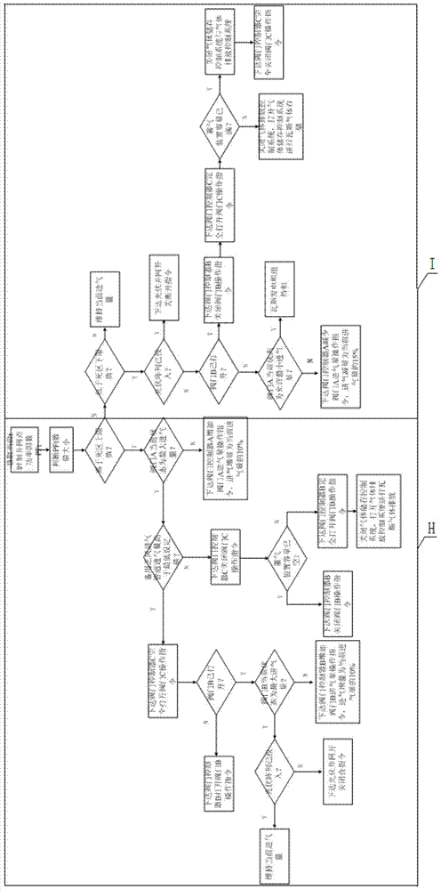
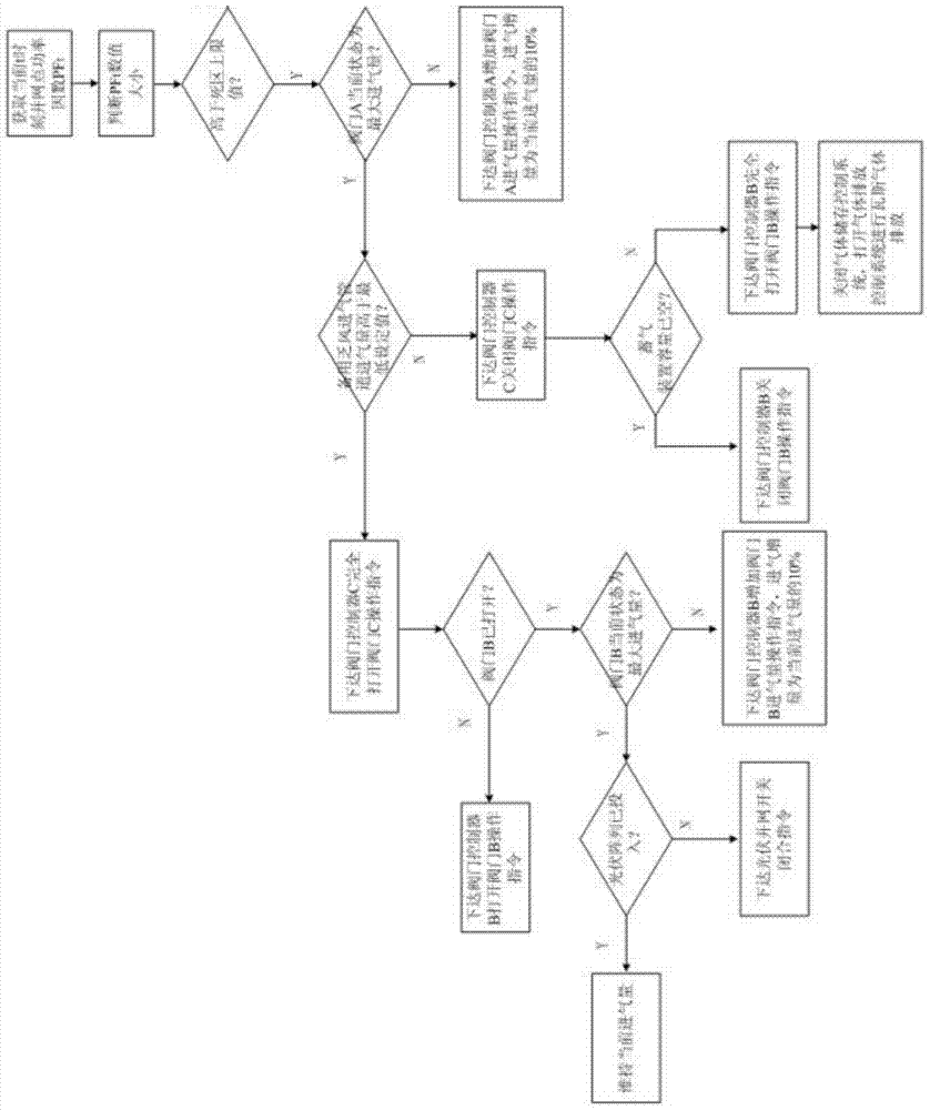
[0032] The present invention will be described in detail below in conjunction with the accompanying drawings and specific embodiments.

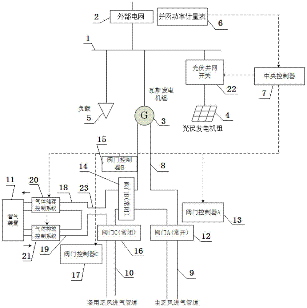
[0033] refer to figure 1 , is a structural schematic diagram of the exhaust gas power generation integrated system based on the power factor assessment of the present invention; the exhaust gas power generation integrated energy system includes an external power grid 2 connected to the bus 1 and powered by a load 5, a gas generator set 3 and Photovoltaic generator set 4 (that is, the photovoltaic array in the figure); the external grid 2 is provided with a grid-connected power meter 6 for collecting power information of a grid-connected point, and the grid-connected power meter 6 is electrically connected to a central controller 7 . The central controller 7 is used to receive the grid-connected point power information sent by the grid-connected power meter 6, and regulate the connection status of the gas generator set 3, the photovoltaic gene...


PUM


Abstract

The invention belongs to the technical field of remote management and control of gas power generation, and discloses a comprehensive system of exhaust gas power generation based on power factor assessment and a control method thereof. The system includes an external grid connected to the busbar, a gas generator set and a photovoltaic array, all of which supply power to the load; a grid-connected power meter is installed at the external grid, and the grid-connected power meter is electrically connected to the central controller; the gas generator set is connected There is a exhaust air intake duct, and the exhaust air intake duct is set as a three-way pipeline with a main intake duct, a main exhaust air intake duct and a spare exhaust air intake duct, and the spare exhaust air intake duct is connected with a gas storage device The ventilation pipe and the gas storage device are connected with the gas storage device on the ventilation pipe; the photovoltaic generator set is electrically connected with the central controller. The grid-connected power meter collects the power information of the grid-connected point and transmits it to the central controller in real time. When the central controller obtains the PFt at that moment, it judges and controls the operation. It can coordinate the exhaust wind generator set and the photovoltaic array in a unified way by integrating the power factor.

Description

technical field [0001] The invention belongs to the technical field of remote management and control of gas power generation, and in particular relates to a comprehensive system of exhaust gas power generation based on power factor assessment and a control method thereof. Background technique [0002] The gas generator set can make full use of exhaust gas, reduce exhaust gas emissions and reduce environmental pollution while realizing comprehensive utilization of energy. It is an environmentally friendly and energy-saving form of power generation that can actively promote the development of clean production energy. Realize the integrated process of coal mining, gas extraction and power generation, and effectively improve the production level. [0003] On the other hand, with the rapid development of society and economy, non-renewable energy sources such as fossil energy are increasingly in short supply, and solar power generation applications are becoming more and more exten...

Claims


Application Information

Patent Timeline
Patent Type & Authority Patents(China)
IPC IPC(8): H02J3/18H02J3/38F02D41/00F02D29/06F02M21/02
CPCY02E10/56Y02E40/30Y02T10/30
Inventor 江金明
Owner 陕西华泰汇丰能源科技有限公司
Why Eureka
Try Eureka