
Automatic sweep-frequency wireless resonant power transmission device and operation method

A technology of automatic frequency sweeping and power transmission, applied in circuits, inductors, electrical components, etc., can solve the problems of high transmission power, component damage, long transmission distance, etc., to achieve strong anti-interference ability, reduce transmission loss, transmission long distance effect

Inactive Publication Date: 2015-12-23
NORTHEAST AGRICULTURAL UNIVERSITY
View PDF4 Cites 5 Cited by
  • Summary
  • Abstract
  • Description
  • Claims
  • Application Information

AI Technical Summary

Problems solved by technology

[0003] So far, the wireless power transmission technology that has come out can be roughly divided into three categories according to its power transmission principle: the first category is based on the principle of electromagnetic induction, which is improved on the traditional transformer, and its transmission power is large but the distance is relatively short.
The second type applies the principle that electromagnetic waves can be transmitted and received, and energy transmission is realized through the transmitting and receiving antennas. The transmission distance is long but the transmission efficiency is low and the directionality is strong.
[0004] In order to make the system obtain higher load absorption power and circuit transmission efficiency, it is necessary to select an appropriate resonant frequency. Deviation from this resonant frequency will reduce the power and efficiency, and the setting of the resonant frequency must consider the frequency characteristics of the circuit components. If the frequency is improper, it may cause damage to components, and the circuit loss will be more

Method used

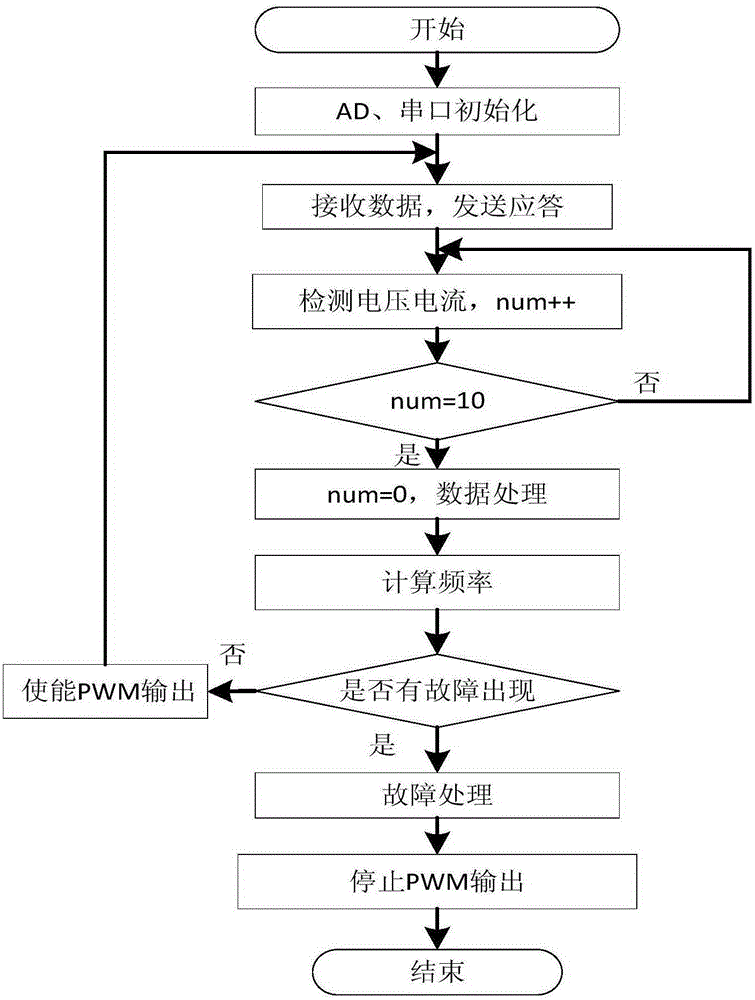
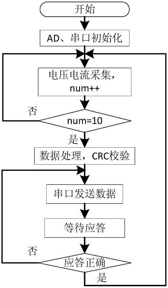

Image

  • Automatic sweep-frequency wireless resonant power transmission device and operation method
  • Automatic sweep-frequency wireless resonant power transmission device and operation method
  • Automatic sweep-frequency wireless resonant power transmission device and operation method

Examples


Embodiment Construction

[0039] The present invention will be described in further detail below in conjunction with the accompanying drawings.

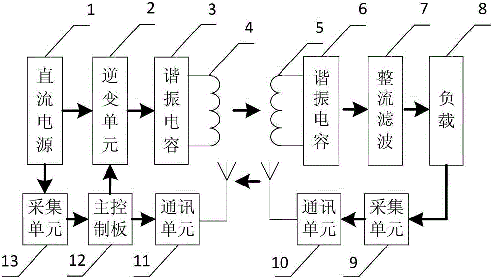
[0040] Such as figure 1 As shown, an automatic frequency scanning wireless resonant power transmission device includes:

[0041] A DC power supply 1 configured to provide DC power to the inverter unit 2;

[0042] The inverter unit 2 is configured to convert direct current into high frequency alternating current, wherein the inverter circuit is such as Figure 4 shown;

[0043] The first resonant capacitor 3 and the second resonant capacitor 6 are configured to generate a resonant circuit with the coil inductance and generate a maximum current;

[0044] The first inductive coil 4 and the second inductive coil 5 are configured to transmit alternating current from the first inductive coil 4 to the second inductive coil 5 through electromagnetic conversion;

[0045] The rectifying and filtering unit 7 is configured to convert high-frequency alternating curren...


PUM


Abstract

The invention discloses an automatic sweep-frequency wireless resonant power transmission device and an operation method. A direct-current power supply, an inverter unit, a first resonant capacitor and a first inductance coil are sequentially and electrically connected in a one-way mode. A second inductance coil, a second resonant capacitor, a rectifier and filter unit and a load are sequentially and electrically connected in a one-way mode. A first acquisition unit is connected in parallel with the direct-current power supply. A second acquisition unit is connected in parallel with the load. Signals of the first acquisition unit, a main control board and the inverter unit are sequentially transmitted in a one-way mode. Signals of the main control board and a first communication unit are transmitted in a two-way mode. Signals of the first communication unit and a second communication unit are transmitted in a two-way mode. Signals of the second communication unit and the second acquisition unit are transmitted in a two-way mode. According to different loads connected, the frequency of alternating current can be automatically adjusted to a frequency maximizing the working efficiency of the system to make the system in a state of resonance. The system is stable, the anti-jamming capability is strong, and the transmission distance is large.

Description

technical field [0001] The present invention relates to the technical field of wireless power transmission and reception, and more specifically relates to the automatic adjustment of the working frequency in a resonant wireless power transmission and reception device and how to automatically maintain the highest efficiency of the system and the voltage and current required by the load. Background technique [0002] With the improvement of human living standards, various electronic and electrical products continue to emerge. They enrich our lives, but various wires and power sockets have also brought us a lot of trouble. At the same time, some special occasions, such as mines, underwater and There are many problems in the use of direct contact transmission through wires in special environments such as the body. Wireless power transfer provides a new solution to the above problems. [0003] So far, the wireless power transmission technology that has come out can be roughly di...

Claims


Application Information

Patent Timeline
IPC IPC(8): H02J17/00H01F38/14H01F27/28
Inventor 王润涛李明王树文张长利刘超吕涛张伶鳦邢晨
Owner NORTHEAST AGRICULTURAL UNIVERSITY
Learn More