
a two-pole generator

A generator, two-pole technology, applied in the shape/style/structure of the magnetic circuit, the rotating parts of the magnetic circuit, the static parts of the magnetic circuit, etc. Material costs, increased manufacturing and processing costs, etc., to achieve the effect of convenient and fast lamination, convenient rotor winding, and improved utilization.

Active Publication Date: 2018-11-16
KUNGFU SCI TECH CO LTD
View PDF3 Cites 0 Cited by
  • Summary
  • Abstract
  • Description
  • Claims
  • Application Information

AI Technical Summary

Problems solved by technology

[0002] The groove shape of the traditional two-pole generator rotor punching is a rectangular structure, which cannot make full use of the effective area of ​​the rotor punching, so that the outer diameter of the rotor punching is larger, and the volume of the generator will also be larger
[0003] Traditional generator stator punching pieces are mostly fan-shaped pieces, and the stator core of the externally press-fitted motor needs a pressure ring and buckle to form a whole, which increases the material cost of the pressure ring and buckle. At the same time, the manufacturing process of the core is also relatively complicated, which increases processing cost
The end of the stator winding of the traditional generator is arc-shaped or triangular, the end of the winding is long, the cost is high, and the overall length of the motor is increased at the same time

Method used


Image

  • a two-pole generator
  • a two-pole generator
  • a two-pole generator

Examples


Embodiment Construction

[0020] The embodiments of the present invention will be described in further detail below in conjunction with the accompanying drawings, but the present embodiments are not intended to limit the present invention, and any similar structures and similar changes of the present invention should be included in the protection scope of the present invention.

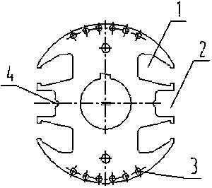
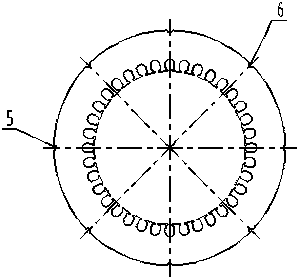
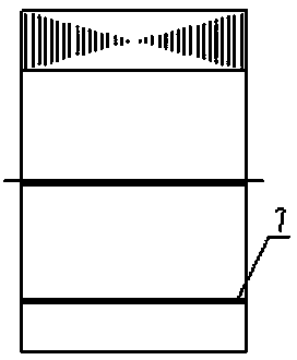
[0021] Such as Figure 1~Figure 5 As shown, the present invention is achieved in this way, a two-pole generator, characterized in that: the rotor punching piece on the generator is an integral punching piece with two-pole special-shaped grooves, the outer circle is an eccentric structure, and the rotor punching piece includes two special-shaped grooves 1. Two square slots 2, 12 damping holes 3 and two semicircular slots 4, two groups of 6 damping holes 3 are symmetrically arranged at both ends of the rotor punching plate, and special-shaped slots 1 are set beside the 6 damping holes 3, and special-shaped A square groove 2 is a...


PUM


Abstract

The present invention discloses a two-pole generator. The structural features of the two-pole generator are that: a rotor punching is a two-pole special-shaped groove overall punching, an excircle of the rotor punching is an eccentric structure, and being different from a conventional square groove, the rotor punching adopts an inclined groove structure; two square grooves and two semi-circular grooves are arranged at the tooth parts, the square grooves are used to reduce the weight and increase the heat radiation area of a rotor iron core, and the semi-circular grooves are used to weld when being used as the rotor iron core, thereby forming weld joints; the rotor iron core forms an entirety via the damping bars and the weld joints, a stator punching is an overall punching, an excircle of the stator punching is equipped with seven semi-circular grooves and a mark groove, and the number of the semi-circular grooves also can be changed according to the actual demands; a stator iron core structure not having the buckle slabs and the clamping rings is adopted to weld in the seven semi-circular grooves and the mark groove of the excircle of the stator punching to form eight weld joints, so that a stator iron core can form a reliable entirety; the stator windings are square windings, and the end parts of the windings are square. The advantages of the present invention are that: the generator is small in size, light in weight and high in cost performance, is convenient to process, and is espeialy suitable for the medium and small size two-pole generator.

Description

technical field [0001] The invention relates to a generator, in particular to a two-pole generator. Background technique [0002] The groove shape of the traditional two-pole generator rotor lamination is a rectangular structure, which cannot make full use of the effective area of ​​the rotor lamination, so that the outer diameter of the rotor lamination is larger, and the volume of the generator will also be larger. [0003] Traditional generator stator punching pieces are mostly fan-shaped pieces, and the stator core of the externally press-fitted motor needs a pressure ring and buckle to form a whole, which increases the material cost of the pressure ring and buckle. At the same time, the manufacturing process of the core is also relatively complicated, which increases Processing costs. The end of the stator winding of the traditional generator is arc-shaped or triangular, the end of the winding is long, the cost is high, and the overall length of the motor is increased ...

Claims


Application Information

Patent Timeline
Patent Type & Authority Patents(China)
IPC IPC(8): H02K1/12H02K1/22
Inventor 杨德华
Owner KUNGFU SCI TECH CO LTD
Learn More