Winding design aimed at winding switching device of permanent magnet synchronous motor

A permanent magnet synchronous motor, winding switching technology, applied to synchronous motors with stationary armature and rotating magnets, shape/style/structure of winding conductors, single motor speed/torque control, etc., can solve inverter problems and limited power supply voltage capacity, high back EMF and other issues

Inactive Publication Date: 2015-12-23
CHONGQING UNIV
View PDF6 Cites 10 Cited by
  • Summary
  • Abstract
  • Description
  • Claims
  • Application Information

AI Technical Summary

Problems solved by technology

[0007] The purpose of the present invention is to solve the problem of limited inverter and power supply voltage capacity by changing the equivalent series turns of the winding through the series-parallel switching of the DC side of the permanent magnet motor control system without increasing the capacity of the inverter. So as to solve the problem of high counter electromotive force when the permanent magnet motor runs at high speed, and improve the speed regulation range of the system

Method used


Image

  • Winding design aimed at winding switching device of permanent magnet synchronous motor
  • Winding design aimed at winding switching device of permanent magnet synchronous motor
  • Winding design aimed at winding switching device of permanent magnet synchronous motor

Examples


Embodiment Construction

[0068] The present invention will be further described below in conjunction with the accompanying drawings and embodiments, but it should not be understood that the scope of the subject matter of the present invention is limited to the following embodiments. Without departing from the above-mentioned technical idea of ​​the present invention, various replacements and changes made according to common technical knowledge and conventional means in this field shall be included in the protection scope of the present invention.

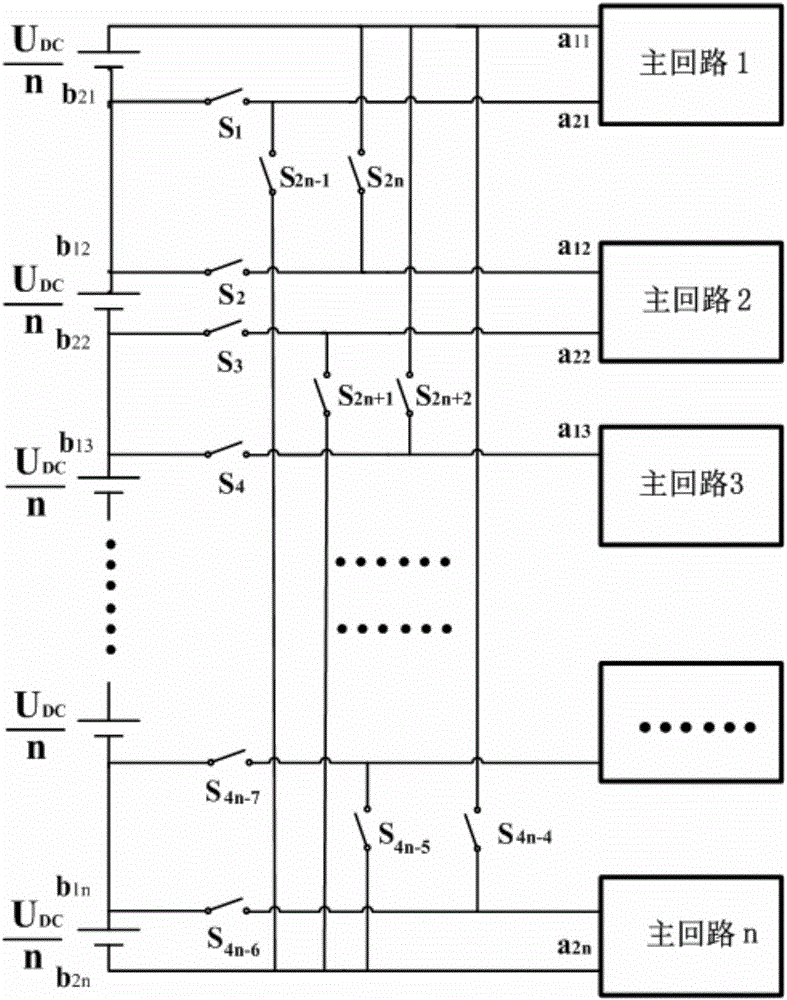
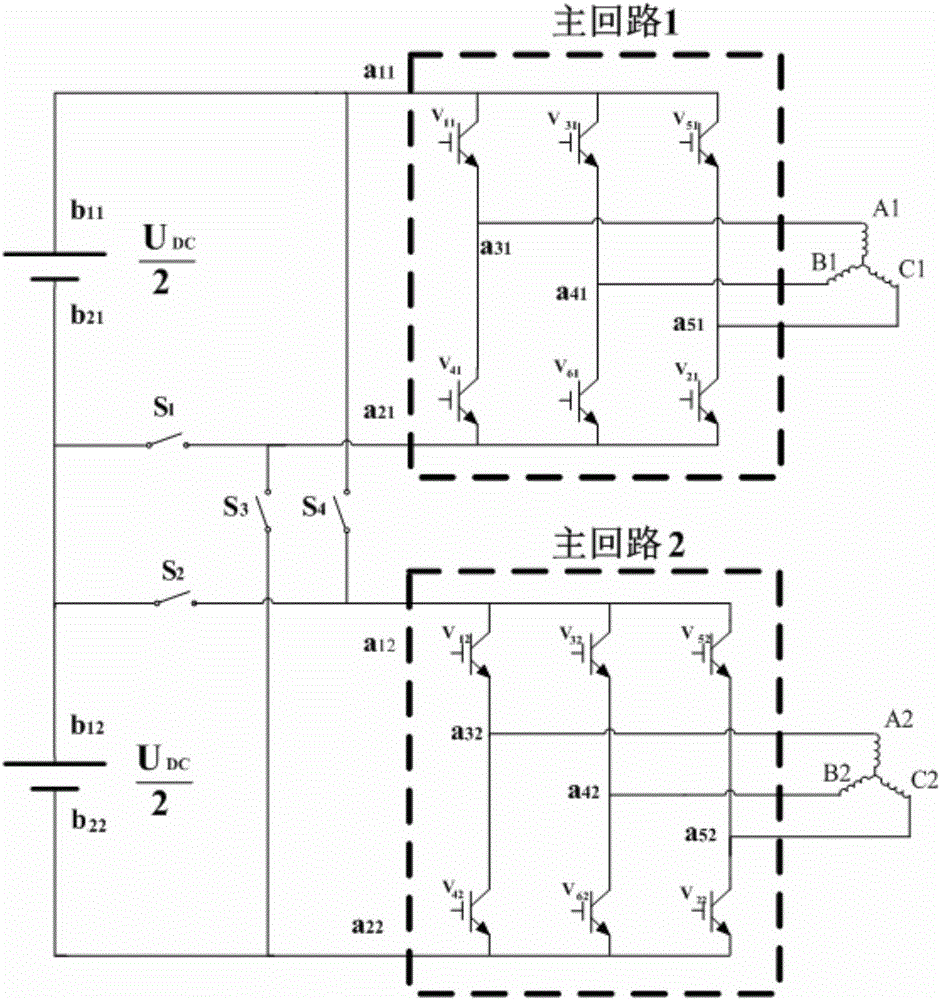
[0069] A winding design for a permanent magnet synchronous motor winding switching device, see figure 1 , The permanent magnet synchronous motor winding switching device includes n main circuit units, n sets of windings and 4n-4 switches, where n≥2.

[0070] Let i = 1, 2, 3, . . . n.

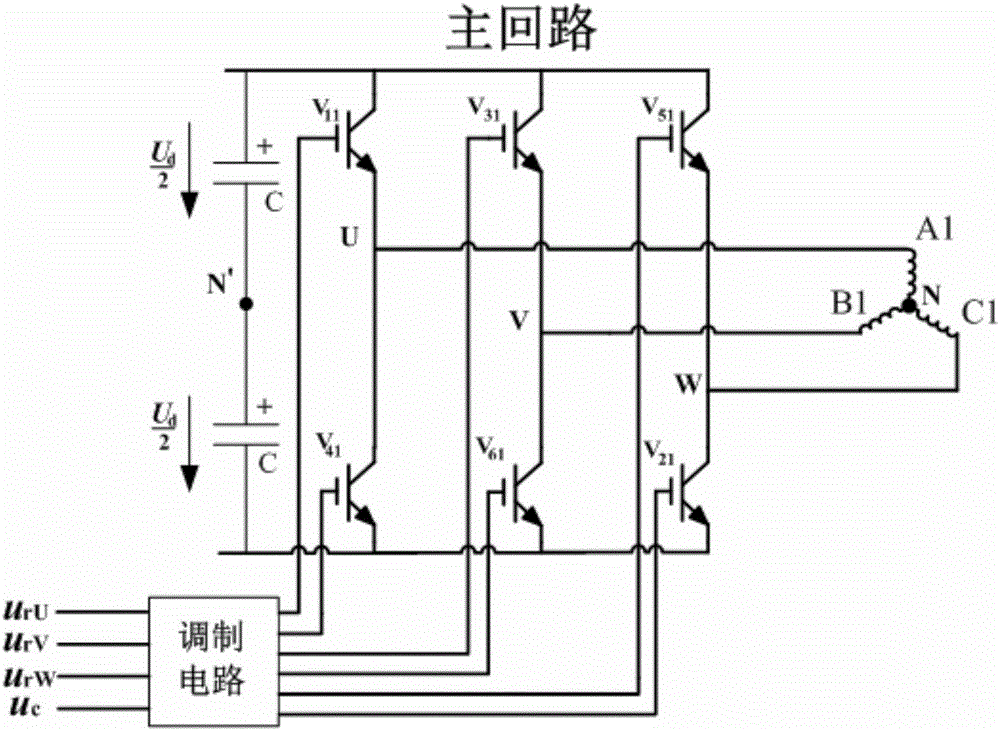
[0071] The i-th main circuit unit includes the 1i-th insulated gate bipolar transistor V 1i , 2i IGBT V 2i , 3i IGBT V 3i , 4i IGBT V 4i , 5i insulated gate bipolar tran...


PUM


Abstract

The invention provides winding design aimed at a winding switching device of a permanent magnet synchronous motor. The device is provided with n sets of windings, corresponding to n main circuit units, and through combined action of (4n-4) switches, series-parallel connection switching of the n sets of windings is realized. A winding method of double-layer lap winding and short-distance distribution is used in the windings. A stator slot of the permanent magnet synchronous motor is embedded with two sets of windings, and the two sets of windings are placed side by side. The winding design is characterized by reducing cost of the switching system, improving reliability of the switching system, improving operation efficiency of a motor, expanding speed regulating range of a motor, and reducing requirement of capacity of the main circuit, providing a selecting principle of rotation speed switchover, and providing a switching strategy for reducing transient pulse current in the switching process.

Description

technical field [0001] The invention relates to the technical field of permanent magnet motors and their control. Background technique [0002] Permanent magnet synchronous motors have many significant advantages such as simple structure, no brushes and slip rings, no electric excitation system, high operational reliability, high power density, and flexible shapes and sizes of motors. In line with the economic development needs of energy saving and emission reduction, it can not only partially replace the traditional electric excitation motor, but also achieve high efficiency that is difficult for electric excitation motors to achieve. Therefore, permanent magnet synchronous motors have been widely used in variable speed drive systems with high requirements such as electric vehicles. As far as the current development level is concerned, compared with the induction motor, the permanent magnet motor is difficult to adjust the excitation of the permanent magnet, and the speed ...

Claims


Application Information

Patent Timeline
Patent Type & Authority Applications(China)
IPC IPC(8): H02K21/14H02K3/12H02K3/28H02P6/08
Inventor 黄嵩徐庆刘刃廖勇
Owner CHONGQING UNIV
Why Eureka
Try Eureka