Air conditioning apparatus inside shielding equipment cabinet

A technology for shielding cabinets and internal air, which is applied in the field of air conditioning devices inside shielding cabinets, which can solve problems such as poor heat dissipation, influence of normal operation of air humidity components, and non-existence of shielding effects, so as to ensure cooling effect, reduce water consumption, The effect of speeding up the cooling process

Inactive Publication Date: 2015-12-23
南京佳旺安环境科技有限公司
6 Cites 2 Cited by

AI-Extracted Technical Summary

Problems solved by technology

The existing common cooling equipment is only limited to fans with poor heat dissipation effect. Correspondingly, when the existing shielded cabinet is running, the staff often open the cab...

Method used

Specifically, the group of cold medium pipelines includes a medium inlet pipe and a medium outlet pipe, the cold medium pipeline is connected to an external air conditioner, and the first evaporator 22 and the second evaporator 23 are connected to the air conditioner respectively. The external unit is connected to ensure the cooling effect.
The inboard of described air inlet is provided with draw-in groove 26, and the belt filter screen near described air inlet is interspersed in described draw-in groove, thereby has eliminated the space between air inlet and belt filter screen, prevents due to The wind resistance of the belt-shaped filter screen is relatively large, which causes air to flow out through the aforementioned gaps.
The present invention makes the air temperature inside the shielding cabinet, the humidity be in the range suitable for the normal operation of electronic components by setting the air-conditioning internal unit and the humidifier connected with the air-conditioning external machine inside the shielding cabinet, and in the shielding cabinet The operating unit dissipates more heat so that when the temperature is at a higher level, the corresponding air humidity is also at a higher level, thereby increasing the heat capacity of the air inside the shielding cabinet, thereby speeding up the heat dissipation process; Filter the air entering the housing. When the part of the belt filter opposite to the air in...

Abstract

The invention relates to an air conditioning apparatus inside a shielding equipment cabinet. The air conditioning apparatus comprises an air conditioner outer machine, an air conditioner inner machine, a humidifier, a temperature sensor, a humidity sensor, a controller, and a pair of diffuser plates. The air conditioner outer machine is connected with the air conditioner inner machine through a circulation pipeline. Both ends of the air conditioner inner machine are provided with an air inlet and an air outlet respectively. The two diffuser plates are symmetrically arranged on both sides of an operation unit. The interior of each diffuser plate is hollowed out and a plurality of air vents are distributed on a side surface of the diffuser plate and lead to the interior of the diffuser plate. The air outlet leads to the interiors of the diffuser plates through a discharge pipeline. The humidifier is arranged on a side of the air conditioner inner machine. The bottom of the air conditioner inner machine is connected with a condensed water discharging pipeline. The condensed water discharging pipeline is connected with the water tank of the humidifier so as to supply water to the humidifier. The air conditioning apparatus enables the air temperature and air humidity inside the shielding equipment cabinet to be within a range suitable for the normal operation of electronic elements.

Application Domain

Technology Topic

Image

  • Air conditioning apparatus inside shielding equipment cabinet
  • Air conditioning apparatus inside shielding equipment cabinet
  • Air conditioning apparatus inside shielding equipment cabinet

Examples

  • Experimental program(1)

Example Embodiment

[0016] The present invention will be further described below with reference to the accompanying drawings and embodiments.
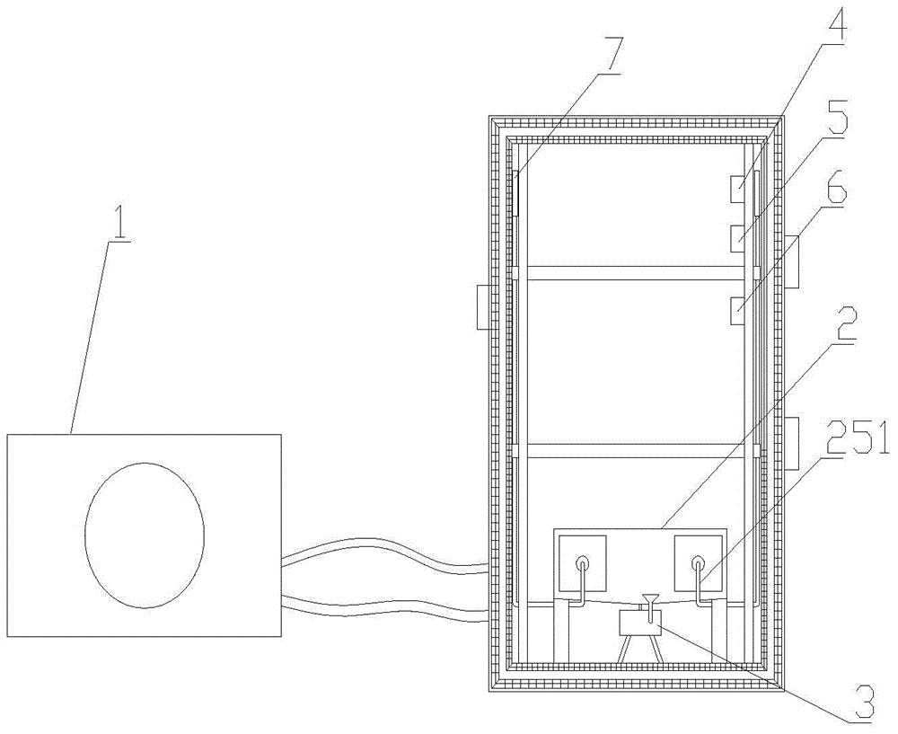
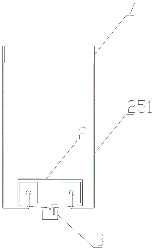
[0017] The upper contents of the shielded cabinet have operating units, such as figure 1 As shown, the air conditioning device inside the shielded cabinet includes an air conditioner outer unit 1, an air conditioner inner unit 2, a humidifier 3, a temperature sensor 4, a humidity sensor 5, a controller 6 and a pair of diffusion plates 7. The air conditioner inner unit 2 is provided with In the inner and lower part of the shielding cabinet, the air conditioner outer unit is connected with the air conditioner inner unit through a circulation pipeline; the two ends of the air conditioner inner unit 2 are respectively 211 air inlets and 212 air outlets, and the two diffusers 7 are symmetrically arranged. On both sides of the operating unit, the diffuser plate 7 is hollowed out inside, and one side is distributed with a number of air outlets communicating with the inside thereof. The air outlets are opposite to the operating unit. The air outlet is connected to the air outlet through the air outlet pipe 251. The diffuser plate communicates internally, so as to diffuse the cold air discharged from the air conditioner to both sides of the operating unit; the humidifier 3 is arranged on one side of the air conditioner, and the bottom of the air conditioner is connected with a The condensed water discharge pipeline 218 is connected with the water tank of the humidifier to provide water for the humidifier; the temperature sensor 4 and the humidity sensor 5 are arranged on one side of the operating unit, and The two are connected to the controller 6 , and the controller 6 is connected to the air conditioner external unit 1 , the air conditioner internal unit 2 and the humidifier 3 .
[0018] The air conditioner internal unit 2 includes a casing 21, a first evaporator 22, a second evaporator 23, a filter mechanism 24 and a fan 25. The two ends of the casing are respectively provided with an air inlet 211 and an air outlet 212. An air duct located in the housing is formed between the air inlet and the air outlet. The air duct is divided into a filter section and a cooling section by the partition plate 213. The filter screen mechanism is arranged in the filter section. The filter screen mechanism 24 It includes a driving wheel 241, a driven wheel 242, an offset wheel 243, a belt-shaped filter screen 244, and a fixed brush 245. The lower part of the filter section corresponds to the shell extending downward to form a dust removal cavity 246. The driving wheel and the driven wheel are arranged longitudinally. On the inside of the air inlet, the biasing wheel is located on the side of the driving wheel and the driven wheel away from the air inlet and at the upper part of the dust removal chamber, and above the dust removal chamber is provided a The offset wheel is close to the dust removal partition 247 on the side of the cooling section; the belt-shaped filter screen is hooped on the driving wheel, the driven wheel and the offset wheel, so that the lower belt-shaped filter screen is introduced into the dust removal chamber, The dust removal partition 247 is connected with a sealing strip 248, and the sealing strip overlaps the belt-shaped filter screen at the offset wheel; the fixed brush 245 is fixedly arranged in the dust removal cavity and has bristles at its ends, so The bristles are in contact with the belt-shaped filter screen located in the dust-removing chamber, so that when the driving wheel rotates so that the belt-shaped filter screen moves relative to the fixed brush, the dust on the belt-shaped filter screen is dusted by the bristles of the fixed brush and falls into the dust-removing chamber; the The bottom of the dust chamber is opened, and an ash collecting basin 249 for collecting dust is inserted at the opening; the first evaporator 22 and the second evaporator 23 are sequentially arranged in the cooling section along the direction of the airflow in the housing, and The two are respectively connected with a set of cold medium pipelines 27; the upper shell corresponding to the first evaporator is raised upward to form a defrosting chamber 221, and the defrosting chamber has a built-in electric heater 222; the bottom shell of the cooling section The casing is provided with a number of drainage holes 214, and a collection bucket 215 and a water storage box 216 connected to the lower end of the collection bucket are arranged on the outside of the casing; The condensed water discharge pipeline 218 is connected; the fan 25 is connected to the inner side of the air outlet, and the air outlet pipeline 251 is connected to the outside of the air outlet.
[0019] The rotating shaft of the driving wheel is connected to a motor (not shown in the figure). Since the filter screen of the air conditioner is relatively light, the low-power motor can drive the belt filter to rotate. The filter in the middle of the belt filter uses The material is the same as that of the common air conditioner filter screen, only the frame is made of soft material, the common air conditioner filter screen is rectangular, and the belt filter screen is annular.
[0020] The inner side of the air inlet is provided with a card slot 26, and the belt filter close to the air inlet is inserted into the card slot, so as to eliminate the gap between the air inlet and the belt filter and prevent the belt filter. The wind resistance of the mesh is large, causing the air to flow out through the aforementioned gaps.
[0021]Specifically, the set of cold medium pipelines includes a medium inlet pipe and a medium outlet pipe, the cold medium pipeline is connected to an external air conditioner unit, and the first evaporator 22 and the second evaporator 23 are respectively connected to the air conditioner external unit Thus ensuring the cooling effect.
[0022] The controller drives the humidifier to operate, so that the relative humidity of the air inside the shielded cabinet is 40%-55%. When the relative humidity is lower than 40%, the electronic components are easy to accumulate static electricity that affects their normal operation. When the relative humidity is higher than 55%, it is easy to cause a local short circuit.
[0023] The controller drives the inner unit of the air conditioner and the outer unit of the air conditioner to operate, so that the air temperature inside the shielded cabinet is between 5°C and 37.8°C.
[0024] When the air temperature measured by the temperature sensor is greater than 35° C., the controller drives the humidifier to operate, so that the relative humidity of the air inside the shielded cabinet is 50%-55%. Increasing the humidity of the air increases the heat capacity of the air so that the airflow inside the shielded cabinet can remove more heat from the operating unit.
[0025] In the present invention, an air conditioner inner unit and a humidifier connected to the air conditioner outer unit are arranged inside the shielding cabinet, so that the air temperature and humidity inside the shielding cabinet are within the range suitable for the normal operation of electronic components, and the operating units in the shielding cabinet dissipate heat. Therefore, when the temperature is at a higher level, the corresponding air humidity is also at a higher level, thereby increasing the heat capacity of the air inside the shielding cabinet, thereby speeding up the heat dissipation process; The air in the body is filtered. When the part of the belt filter opposite to the air inlet has a lot of dust, which leads to large wind resistance and poor filtering effect, the belt filter can be rotated by the motor and the driving wheel to make the clean part and the filter. The air inlet continues to carry out the filtering operation relatively, thus prolonging the cleaning cycle of the filter screen; by setting the fixed brush in the dust removal chamber at the lower part of the belt filter screen, the dust on the filter screen can be removed in time without disassembly; Setting the first evaporator upstream of the second evaporator can remove a large amount of moisture in the air outside the first evaporator, thereby ensuring the cooling effect of the second evaporator; by placing alum in the water storage box, the collection from the evaporator The suspended matter in the formed condensed water is deposited in the water storage box, and the overflowing clean water is supplemented into the humidifier to reduce the water consumption caused by maintaining the air humidity inside the shielded cabinet; The air circulation between the dust removal chamber and the cooling section can only be achieved through two layers of filters, so as to ensure that the dust in the dust removal chamber will not spread to the cooling section. The entire inner unit can clean up the dust generated during the operation of the inner unit of the air conditioner, which is more convenient to operate.

PUM

no PUM

Description & Claims & Application Information

We can also present the details of the Description, Claims and Application information to help users get a comprehensive understanding of the technical details of the patent, such as background art, summary of invention, brief description of drawings, description of embodiments, and other original content. On the other hand, users can also determine the specific scope of protection of the technology through the list of claims; as well as understand the changes in the life cycle of the technology with the presentation of the patent timeline. Login to view more.

Similar technology patents

Preparation method of silver-tungsten composite copper alloy electric contact material

PendingCN114496621AGood electrical and thermal conductivityLarge heat capacityContact materialsMetallic material coating processesTungstenOxide
Owner:WENZHOU LONGSUN ELECTRICAL ALLOY CO LTD

Gasification burner

ActiveCN104279558ALarge heat capacityExtended service lifeLiquid fuel burnerCombustorHeat resistance
Owner:YANTAI LONGYUAN POWER TECH

Oil gasifier and oil burner

InactiveCN102788350ACompact structureLarge heat capacityBurnersOil burnerFuel oil
Owner:YANTAI LONGYUAN POWER TECH

Solar heat cabinet

PendingCN114593453ALarge heat capacityCompact structureSolar heating energySolar heat storageCollector deviceElectric energy
Owner:NANJING YUNENG NEW ENERGY TECH

Classification and recommendation of technical efficacy words

  • Large heat capacity

Perpendicular magnetic recording medium and manufacturing method of the same

InactiveUS20120052330A1Large heat capacityTemperature of substrate is reducedRecord information storageCoatingsPhysicsRecording density
Owner:HITACHI LTD

Card connector

ActiveUS20110130029A1Improve heat dissipation efficiencyLarge heat capacityCoupling device detailsSensing record carriersHeat sinkIntegrated circuit
Owner:YAMAICHI ELECTRONICS

Auxiliary braking device for magnetic rheological body petroleum drilling rig

ActiveCN1945047ALarge amount of liquidLarge heat capacityLiquid resistance brakesPetroleumConductive materials
Owner:BC P INC CHINA NAT PETROLEUM CORP +1

Three-grade coal mine allowable emulsified explosive and preparation method thereof

ActiveCN102503742AGood effectLarge heat capacityExplosivesWater in oilChemistry
Owner:云南锐达民爆有限责任公司
Why Eureka
Try Eureka