Magnetron

A technology of magnetrons and magnets, applied in the field of magnetrons, can solve problems such as no help

Inactive Publication Date: 2015-12-23
朴秀用
View PDF12 Cites 4 Cited by
  • Summary
  • Abstract
  • Description
  • Claims
  • Application Information

AI Technical Summary

Problems solved by technology

Therefore, continuous processing to produce magnetrons is impractical and typically requires batch-job processing
And said 4G magnetrons use diffe...

Method used


Image

  • Magnetron
  • Magnetron
  • Magnetron

Examples


Embodiment Construction

[0084] It should be understood that the drawings and descriptions provided herein may have been simplified to illustrate elements for a clear understanding of the present invention, while for the purpose of clarity, other elements found in typical similar devices, systems and methods have been deleted. Accordingly, those skilled in the art will recognize that other elements and / or steps may be desirable and / or necessary to implement the apparatus systems and methods described herein. However, since these elements and steps are known in the art and they do not contribute to a better understanding of the present invention, a discussion of these elements and steps may not be provided here. The present disclosure is considered to inherently include all such elements, variations, and modifications of disclosed elements and methods known to those skilled in the art.

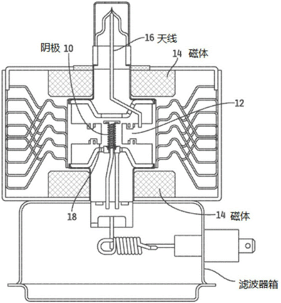
[0085] For example a magnetron in the cross-sectional view shown in Figure 1, comprising an electron tube, produces ...


PUM


Abstract

A 4G magnetron is disclosed. The magnetron may include an anode comprising a cylindrical member and anode vanes disposed within the cylindrical member which define resonant cavities therebetween, and a dispenser cathode, suitable for heating and located coaxially within said anode. The magnetron may operate in a temperature range of about 850-1050 DEG C. The magnetron may include conductive cooling. The magnetron may comprise inventive anode and cathode structures. A method for preparing a plurality of magnetron tubes substantially simultaneously is further provided.

Description

[0001] Cross References to Related Applications [0002] This application claims priority from the following applications: U.S. Provisional Application No. 61 / 771559, filed March 1, 2013, titled Conduction Cooling of Magnetrons for Electrodeless Lamps; U.S. Provisional Application No. 61 / 771594, filed on March 1, 2013, and the name of the invention is low electromagnetic leakage magnetron; U.S. provisional application, application number is 61 / 771602, filed on March 1, 2013, and the name of the invention is 4G magnetron Tube; U.S. provisional application, application number 61 / 779107, filing date March 13, 2013, name of the invention 4G magnetron; U.S. provisional application, application number 61 / 771613, filing date March 1, 2013, name of the invention It is the processing chamber for 4G magnetron. [0003] This application is related to a PCT application entitled "Sulphur Lamp", filed on the same date as this application by the inventor of this application. technical field...

Claims


Application Information

Patent Timeline
IPC IPC(8): H01J25/50
CPCH01J9/385H01J23/05H01J23/12H01J1/28H01J25/587H01J23/005H01J9/18H01J9/26H01J25/50
Inventor 朴秀用
Owner 朴秀用
Why Eureka
Try Eureka