Al technical title is built by PatSnap Al team. It summarizes the technical point description of the patent document.
A technology of testing equipment and testing methods, applied in the field of testing, can solve the problems of inconvenient follow-up process and market introduction
Inactive Publication Date: 2015-12-30
SHENZHEN SUNWAY COMM
View PDF5 Cites 3 Cited by
Summary
Abstract
Description
Claims
Application Information
AI Technical Summary
This helps you quickly interpret patents by identifying the three key elements:
Problems solved by technology
Method used
Benefits of technology
Problems solved by technology
This solution has a certain fool-proof function by marking defective products. When defective products are pushed to the good product area by mistake due to signal delay or system failure, they may be discovered and re-sorted in the subsequent process. Inconvenience is caused, and there is still the possibility that defective products may be put on the market as good products
Method used
Image
Click on the blue label to locate the original text in one second.
Reading with bidirectional positioning of images and text.
Examples
Embodiment 1
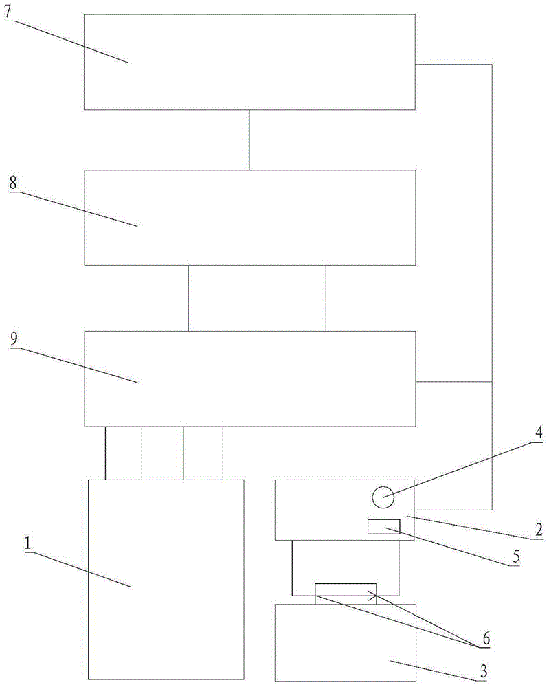
[0031] Please refer to figure 1 , Embodiment 1 of the present invention is: a kind of anti-fool test equipment, including test fixture 1, control box 2, defective product feeding box 3, control equipment 7, network analyzer 8 and switch box 9, described control box 2 Be provided with lamp 4 and buzzer 5, the feed opening of described defective product feeding box 3 is provided with a photoelectric switch 6, and described control box 2 is connected with photoelectric switch 6, and described switch box 9 is connected with described control equipment 7, network. The analyzer 8, the test fixture 1 and the control box 2 are connected.
[0032] The control device 7, such as a computer, is used for installing control software. The control software can control the test process, analyze the test data and judge whether the product is good or bad. The network analyzer 8 is a test instrument, which is connected to the control device 7 and the test fixture 1. The switch box 9 is used to ...
Embodiment 2
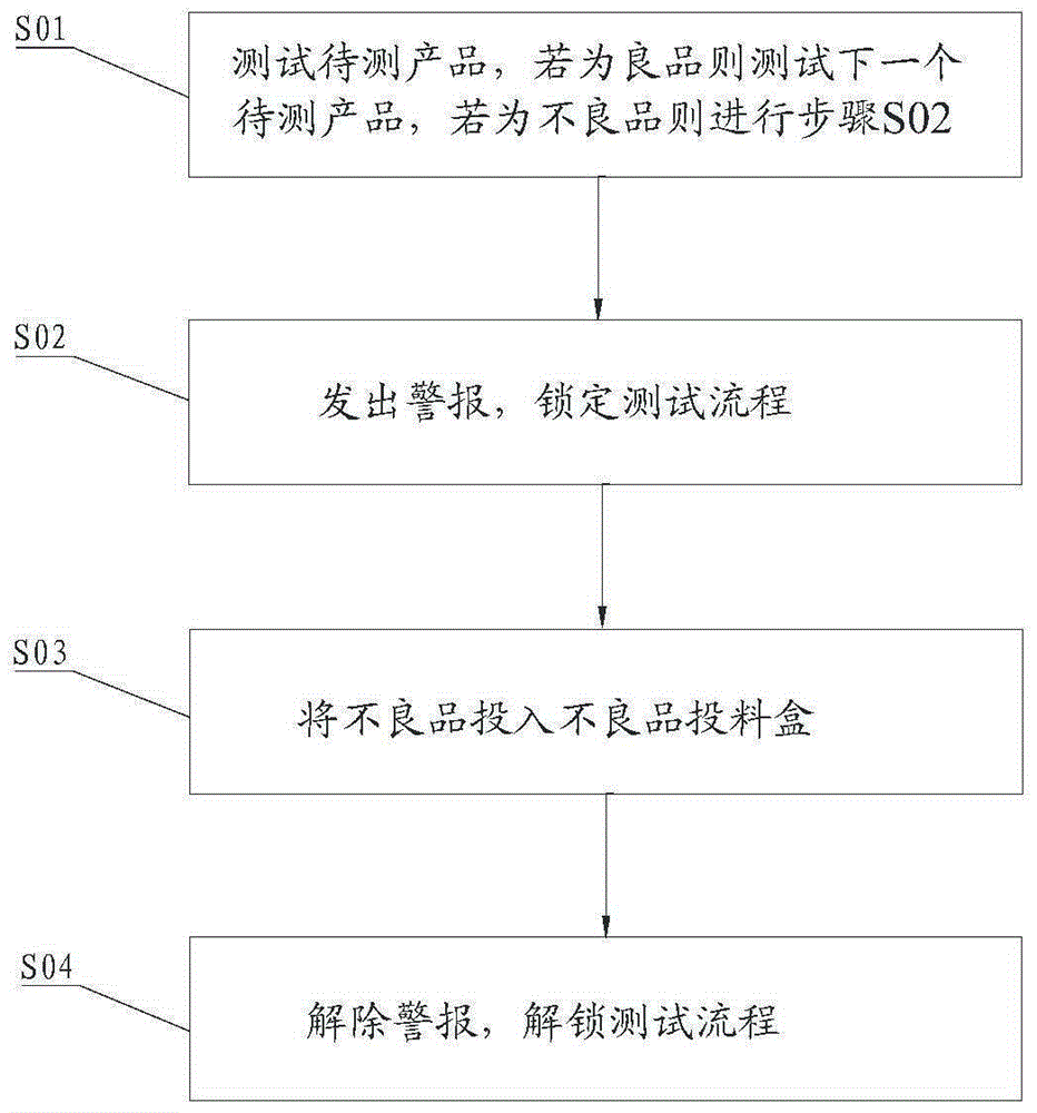
[0034] Please refer to figure 2 , Embodiment 2 of the present invention is: a kind of method that is suitable for the fool-proof test of the fool-proof test equipment of embodiment 1, can be used for qualified detection such as electronic equipment, mechanical parts, and the steps are as follows:
[0035] When starting the test, the control software installed in the control device 7 controls the control box 2 to output an action signal to start the test to the switch box 9, so that the test fixture 1 and the network analyzer 8 start testing, and the control software obtains the information of the product through TCP / IP. Test the data, and judge whether the product is good or bad, if it is a good product, then carry out the test of the next product to be tested, if it is a defective product, then notify the control box 2, make the light 4 in the control box 2 light red, and the buzzer 5 Make a sound, and let the control box 2 output an action signal to stop the test to the swi...
PUM
Abstract
The invention discloses fool-proof test equipment. The fool-proof test equipment comprises a test fixture, a control box and a defective product feed box, wherein the control box is provided with a lamp and a buzzer, and a photoelectric switch is arranged at a feed port of the defective product feed box and connected with the control box. The invention further discloses a fool-proof test method. The method comprises following steps: S01, a to-be-tested product is tested, if the to-be-tested product is a non-defective product, next to-be-tested product is tested, and if the to-be-tested product is a defective product, a step S02 is executed; S02, an alarm is sent out, and a test process is locked; S03, the defective product is fed into the defective product feed box; S04, the alarm is released, and the test process is unlocked. With the arrangement of the lamp and the buzzer, the alarm can be sent out when the defective product is tested; with the arrangement of the photoelectric switch, the defective product are all fed into the defective product feed box, can be prevented from being mistakenly placed in a non-defective product area by an operator in a production test process and cannot be mixed in the non-defective products, and customer complaint and company loss are avoided.
Description
technical field [0001] The invention relates to the field of testing, in particular to a fool-proof testing device and method. Background technique [0002] Existing production online testing mostly uses area marks for defective products and good products to distinguish defective products from good products. The disadvantage of distinguishing defective products from good products by area identification is that it is easy to misplace areas to cause good and defective products to mix, and there is no obvious fool-proof function. [0003] In the patent document with the application number of 201520029613.8, a FPC short-circuit fool-proof testing machine that can automatically distinguish good products from defective products is disclosed. The test products are pushed to the good product area or the defective product area, and the products pushed to the good product area are sent away through the slideway, and the products pushed to the defective product area will be marked wit...
Claims
Application Information
Patent Timeline
Application Date:The date an application was filed.
Publication Date:The date a patent or application was officially published.
First Publication Date:The earliest publication date of a patent with the same application number.
Issue Date:Publication date of the patent grant document.
PCT Entry Date:The Entry date of PCT National Phase.
Estimated Expiry Date:The statutory expiry date of a patent right according to the Patent Law, and it is the longest term of protection that the patent right can achieve without the termination of the patent right due to other reasons(Term extension factor has been taken into account ).
Invalid Date:Actual expiry date is based on effective date or publication date of legal transaction data of invalid patent.