Z-pin reinforced composite grid structure and manufacturing method thereof

A technology for reinforcing composite materials and grid structures, which is applied in the field of composite material reinforcement, can solve problems such as strength reduction at joints, and achieve the effects of improving uneven thickness, improving connection strength and fatigue resistance.

Active Publication Date: 2015-12-30
NANJING UNIV OF AERONAUTICS & ASTRONAUTICS
View PDF4 Cites 8 Cited by
  • Summary
  • Abstract
  • Description
  • Claims
  • Application Information

AI Technical Summary

Problems solved by technology

[0003] At present, the grid structure in China is mainly formed by manual laying and automatic winding. The continuous laying or winding of ribs leads to the accumulation of prepreg yarn in the node area and the fiber overhead, resulting in a decrease in the strength of the node.

Method used


Image

  • Z-pin reinforced composite grid structure and manufacturing method thereof
  • Z-pin reinforced composite grid structure and manufacturing method thereof
  • Z-pin reinforced composite grid structure and manufacturing method thereof

Examples


no. 1 example

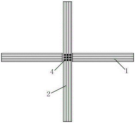
[0035] The first embodiment: as figure 2 as shown,

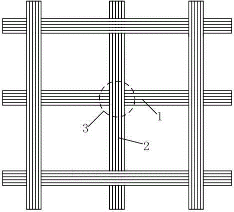
[0036] A Z-pin reinforced composite material grid structure of the present invention comprises a transverse bar 1 and a longitudinal bar 2, and a node 3 is formed at the intersection of the transverse bar 1 and the longitudinal bar 2, wherein: the transverse bar 1 and the longitudinal bar 2 adopt "shearing-continuation" in sequence "process, and implant Z-pin4 at the intersection, that is, node 3, to improve the connection strength of the composite grid structure;

[0037] The process of "cutting-continuing laying" is: in each layer of composite material grid structure, only one node of the transverse reinforcement 1 and longitudinal reinforcement 2 is laid, and the other is cut on both sides of the node, so that the thickness of each node is the same as that of the transverse reinforcement 1 , The thickness of the remaining parts on the longitudinal rib 2 is consistent.

[0038] In the embodiment, the implantation direct...

no. 2 example

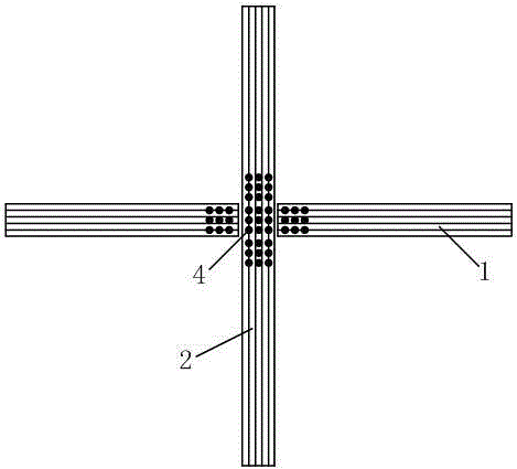
[0051] The second embodiment: as image 3 as shown,

[0052] In the embodiment, the Z-pin4 is also implanted in the parts of the transverse rib 1 and the longitudinal rib 2 close to the node 3 .

[0053] The parts not described are the same as the first embodiment.

[0054] Compared with the first embodiment, this embodiment implants more Z-pin4, the range is wider, and the connection strength is higher.

no. 3 example

[0055] The third embodiment: as Figure 4 as shown,

[0056] In the embodiment, the angle part formed by the node 3 and the transverse rib 1 and the longitudinal rib 2 is paved with a reinforcing plate 5 made of the same material as the transverse rib 1 and the longitudinal rib 2 .

[0057] The parts not mentioned are the same as the second embodiment.

[0058]Compared with the second embodiment, this embodiment is compared with the first embodiment, and this embodiment adds a reinforcing plate 5 to further enhance the connection strength at the nodes.


PUM


Abstract

The invention relates to a Z-pin reinforced composite grid structure and a manufacturing method thereof, belonging to the technical field of fibrous composite reinforcement. The manufacturing method comprises the following steps: planning movement locus of a fiber placement head by a design procedure through a specially-designed grid fiber placement device, and overlaying a grid structure on a grid forming mould by adopting a shearing-continuing placement process; preparing high-performance Z-pin by an advanced pultrusion device, designing a Z-pin parameter, and implanting the Z-pin in a foam prefab; implanting the Z-pin at the structure node part of a grid by ultrasonic implant equipment; and reinforcing the Z-pin reinforced composite grid stiffened structure. According to the invention, the problems of uniform thickness caused by repeated prepreg layering and layered bridging resulted from crossed fiber layers at the node parts can be solved, connection strength and anti-fatigue performance of the node parts also can be obviously enhanced, and Z-pin is light, high in strength and small in fiber damage.

Description

technical field [0001] The invention relates to the technical field of composite material reinforcement, in particular to a Z-pin reinforced composite material grid structure and a manufacturing method thereof. Background technique [0002] Composite grid structure has high specific strength and specific stiffness, and is one of the important aerospace lightweight structures. Its advantages are: (1) Its own topology optimization is good, compared with other composite material structures, it can obtain a higher section moment of inertia, and has higher bending and buckling resistance; (2) One-way composite material reinforcement Ribs have no material matching problems, no delamination and other phenomena, and have high damage tolerance and fatigue resistance. Under loads, especially impact loads, cracks are not easy to propagate even if the ribs are damaged. , to overcome the defect that the laminate structure is easy to delaminate; (3) It is an open structure that overcomes...

Claims


Application Information

Patent Timeline
Patent Type & Authority Applications(China)
IPC IPC(8): B29C70/06B29C70/30B29C70/54
CPCB29C70/06B29C70/30B29C70/54
Inventor 李勇还大军李吻肖军
Owner NANJING UNIV OF AERONAUTICS & ASTRONAUTICS
Why Eureka
Try Eureka