Internal temperature control liquid piston device capable of isothermally compressing and releasing air on basis of air storage units

A liquid piston, gas storage technology, applied in machines/engines, non-displacement pumps, mechanical equipment, etc., can solve problems such as large energy loss, and achieve the effect of improving efficiency, reducing friction, and reducing friction

Active Publication Date: 2015-12-30
NORTH CHINA ELECTRIC POWER UNIV (BAODING)
View PDF5 Cites 9 Cited by
  • Summary
  • Abstract
  • Description
  • Claims
  • Application Information

AI Technical Summary

Problems solved by technology

[0005] Aiming at the problem of heat loss in the compression process of compressed air energy storage and large energy loss due to pressure drop caused by low temperature during expansion, the present invention proposes an internal temperature-controlled liquid piston device based on the gas storage unit to realize gas isothermal scaling, including: a or a plurality of liquid piston chambers composed of pressure vessels, and high-pressure gas pipelines and low-pressure gas pipelines connected to the liquid piston chambers through gas valves; the lower part of the liquid piston chambers is connected to external hydraulic equipment through liquid valves; One or more gas storage units; multiple gas storage units operate independently or in cascade arrangement, between two adjacent gas storage units arranged in cascade, the gas overflow position of the lower gas storage unit is located in the cascaded The bottom or inside o

Method used


Image

  • Internal temperature control liquid piston device capable of isothermally compressing and releasing air on basis of air storage units
  • Internal temperature control liquid piston device capable of isothermally compressing and releasing air on basis of air storage units
  • Internal temperature control liquid piston device capable of isothermally compressing and releasing air on basis of air storage units

Examples


Embodiment Construction

[0031] The embodiments will be described in detail below in conjunction with the accompanying drawings.

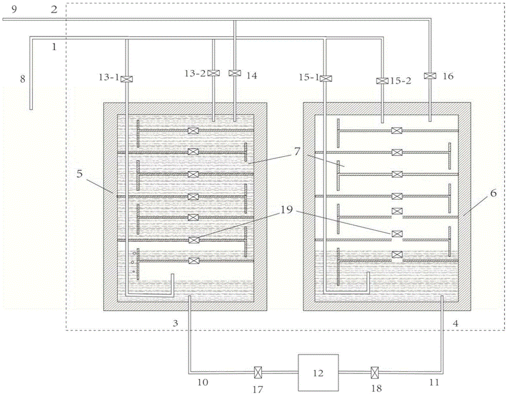
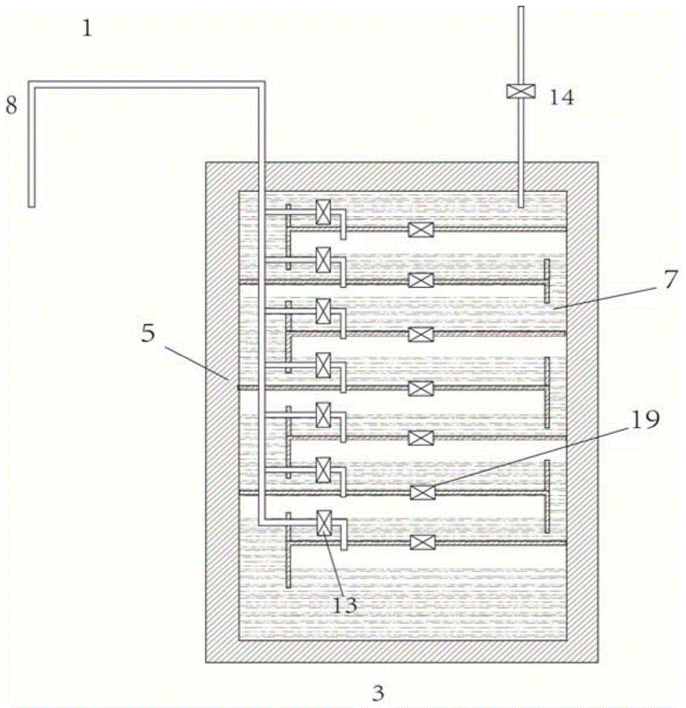
[0032] figure 1 It is a scheme of an internal temperature-controlled liquid piston device that realizes gas isothermal scaling. The device is composed of a first liquid piston chamber 5, a second liquid piston chamber 6, several gas storage units 7 in the chamber, a high-pressure gas pipeline 8, a low-pressure gas pipeline 9, a first liquid pipeline 10, a second liquid pipeline 11, and a gas valve. 13-16, liquid valves 17-18, and the isolation valve 19 of the gas storage unit; wherein the first liquid piston chamber 5 is connected to the high-pressure gas pipeline 8 and the The low-pressure gas pipeline 9 is connected, and the second liquid piston chamber 6 is respectively connected with the high-pressure gas pipeline 8 and the low-pressure gas pipeline 9 through gas valves 15 and 16; multiple chambers are respectively arranged in the first liquid piston chamber 5 and the...


PUM


Abstract

The invention belongs to the technical field of compressed air energy storage, and particularly relates to an internal temperature control liquid piston device capable of isothermally compressing and releasing air on the basis of air storage units. The device comprises one or more liquid piston cavities formed by pressure containers, and a high-pressure air pipeline and a low-pressure air pipeline, which are connected with the liquid piston cavities through air valves, wherein the lower parts of the liquid piston cavities are connected to external hydraulic equipment through liquid valves; one or more air storage units are arranged in each liquid piston cavity; the air storage units independently run respectively, or are cascaded to run; a top valve is arranged between every two adjacent air storage units; the low-pressure air pipeline is connected with the inner tops of the liquid piston cavities; if the air storage units independently run respectively, the high-pressure air pipeline is connected with each air storage unit; if the air storage units are cascaded to run, the high-pressure air pipeline is divided into two branches, the first branch is connected with the inner bottoms of the liquid piston cavities, and the second branch is connected with the inner tops of the liquid piston cavities.

Description

technical field [0001] The invention belongs to the technical field of compressed air energy storage, and in particular relates to an internal temperature-controlled liquid piston device that realizes gas isothermal scaling based on a gas storage unit. Background technique [0002] Energy storage technology has been regarded as an important part of the grid operation process, and compressed air energy storage is widely used. However, compressed air energy storage has certain limitations. The main disadvantage of compressed air energy storage is that it usually cooperates with gas turbines, consumes gas, causes environmental pollution, is easy to leak, has low energy density, and when air is compressed and expanded, the temperature changes drastically. The damage to the equipment is relatively large, resulting in high maintenance costs. [0003] In recent years, researches have applied liquid pistons to compressed air energy storage to solve the environmental pollution probl...

Claims


Application Information

Patent Timeline
IPC IPC(8): F04F1/10
Inventor 姜彤郑祥常陈伟丽童潇何旭洁傅昊
Owner NORTH CHINA ELECTRIC POWER UNIV (BAODING)
Why Eureka
Try Eureka