
Car-mounted laser radar tunnel detection system, autonomous positioning method based on tunnel detection system and tunnel hazard detection method

A vehicle-mounted laser radar and detection system technology, applied in the field of tunnel monitoring and maintenance, can solve the problems of weak satellite positioning signal, difficult tunnel inner wall seepage, water immersion, water damage disaster, difficult to solve actual detection and other problems

Inactive Publication Date: 2015-12-30
尹栋
View PDF5 Cites 25 Cited by
  • Summary
  • Abstract
  • Description
  • Claims
  • Application Information

AI Technical Summary

Problems solved by technology

However, in a long tunnel environment, the satellite positioning signal is generally weak or completely absent. Therefore, it is difficult to solve the actual detection problem in the actual tunnel measurement by relying on satellite positioning to determine the location of the disaster in the tunnel.
In addition, the current tunnel detection method based on visible light and radar images is more common to find and identify surface cracks, fractures, or physical changes in deformation, but this method is difficult to detect water seepage, water immersion, and water damage on the inner wall of the tunnel based on images

Method used


Image

  • Car-mounted laser radar tunnel detection system, autonomous positioning method based on tunnel detection system and tunnel hazard detection method
  • Car-mounted laser radar tunnel detection system, autonomous positioning method based on tunnel detection system and tunnel hazard detection method
  • Car-mounted laser radar tunnel detection system, autonomous positioning method based on tunnel detection system and tunnel hazard detection method

Examples


Embodiment Construction

[0050] The present invention will be further described in detail below in conjunction with the accompanying drawings and specific embodiments.

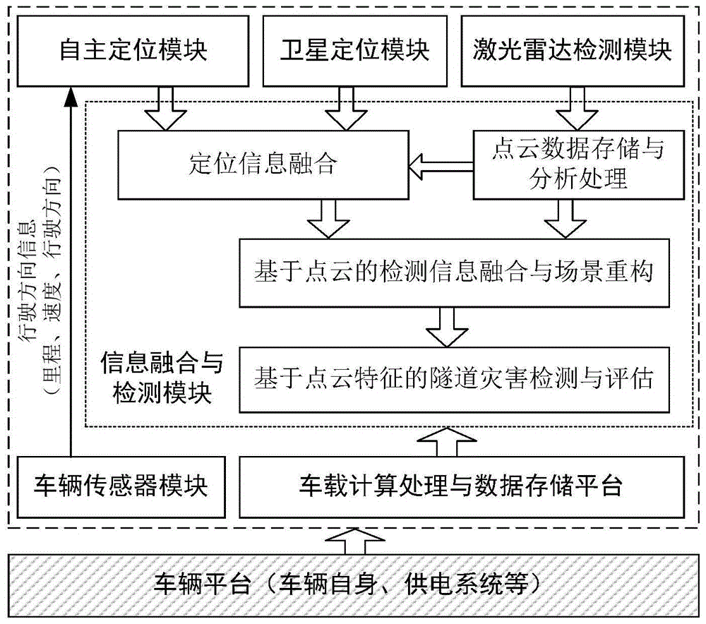
[0051] Such as figure 1 As shown, the vehicle-mounted lidar tunnel detection system based on autonomous positioning of the present invention includes:

[0052] The vehicle platform is used to provide the necessary vehicle operating environment and energy supply for the operation of the detection system.

[0053] The positioning module includes an autonomous positioning module and a satellite positioning module; the satellite positioning module is used for positioning the vehicle platform when the satellite positioning signal can be received, and the autonomous positioning module is used for positioning the vehicle in a position where satellite positioning cannot be performed in the tunnel. Since the satellite positioning signal is weak or even unreceivable in a long tunnel (for example: greater than 2km), it is necessary to rely on t...


PUM


Abstract

The invention relates to a car-mounted laser radar tunnel detection system, an autonomous positioning method based on the tunnel detection system and a tunnel hazard detection method. The detection system comprises a vehicle platform, a positioning module, a laser radar detection module and an information fusion and detection module, wherein the vehicle platform is used for providing a vehicle running environment and energy supply; the positioning module comprises an autonomous positioning module and a satellite positioning module; the satellite positioning module can position the vehicle platform when a satellite positioning signal is received, and the autonomous positioning module can position the position of a vehicle which cannot be positioned by a satellite in a tunnel; the laser radar detection module is used for detecting the surface of the tunnel by utilizing laser; the information fusion and detection module is used for analyzing, processing and fusing position information of the autonomous positioning module / satellite positioning module and the measurement information of the laser radar detection module. The autonomous positioning method is a positioning method suitable for the detection system. The tunnel hazard detection method is a detection method based on the tunnel detection system. The car-mounted laser radar tunnel detection system has the advantages of high detection efficiency, capability of carrying out the real-time monitoring and the like.

Description

technical field [0001] The invention mainly relates to the technical field of tunnel monitoring and maintenance, in particular to a vehicle-mounted lidar tunnel detection system and an autonomous positioning method based on autonomous positioning. Background technique [0002] With the surge of expressway load in my country and the extension of tunnel operation time, how to quickly and effectively monitor existing tunnels to ensure the safety of expressway operation has increasingly become the focus of attention of expressway managers and technicians. [0003] From construction to destruction, tunnels usually go through three stages: deformation, cracking and collapse. Deformation is the first step in failure, and the accumulation of deformation to a certain extent will lead to crack damage, which will aggravate with the increase of deformation and eventually lead to collapse. Through the monitoring of deformation, hidden dangers can be discovered in time, whether the crack...

Claims


Application Information

Patent Timeline
IPC IPC(8): G01N21/88G01B11/16
Inventor 尹栋尹喜林
Owner 尹栋
Learn More