Touch screen, display device and display driving method of display device

A technology of a display device and a touch screen, which is applied to the touch screen, the display device and the display driving field of the display device, can solve the problems of disconnection, disconnection, and large thickness of the touch electrode, and achieve the effect of reducing the thickness and avoiding the disconnection.

Active Publication Date: 2015-12-30
BOE TECH GRP CO LTD
View PDF6 Cites 12 Cited by
  • Summary
  • Abstract
  • Description
  • Claims
  • Application Information

AI Technical Summary

Problems solved by technology

However, the optical density of the black photoresist layer is proportional to its thickness. In order to achieve a good light-shielding effect, the thickness of the black photoresist layer is generally set to about 1 μm. If the thickness of the black photoresist layer is large, it is easy to cause the touch electrode to be broken. line problem
[0005] Therefore, how to reduce the thickness of the non-black frame on the premise of ensuring a good light-shielding effect, so as to avoid the problem of disconnection of the touch electrodes, is a technical problem urgently needed to be solved by those skilled in the art.

Method used


Image

  • Touch screen, display device and display driving method of display device
  • Touch screen, display device and display driving method of display device
  • Touch screen, display device and display driving method of display device

Examples


example 1

[0058] Example 1: The resistance change sensor detects whether the resistance of the low-reflectivity conductive layer changes when the power button is pressed for 2s to 3s.

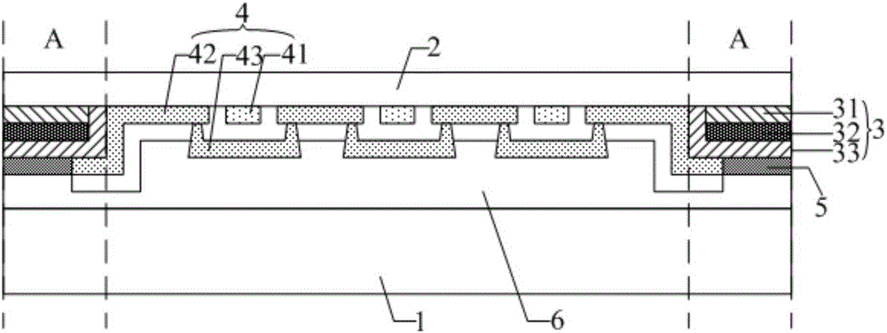
[0059] In specific implementation, in the above-mentioned display device provided by the embodiment of the present invention, such as Figure 4 As shown, it may also include: a power key 404 for controlling the touch screen 401 to be turned on or off; when the resistance change sensor 402 senses that the resistance changes, that is, when the touch function of the touch screen 401 is abnormal, the resistance change sensor 402 outputs to the drive circuit 403 The first control signal controls the driving circuit 403 to drive the display panel to display the first display interface. Preferably, the first display interface displays an option: press and hold the power button for 5s to 6s to dial an emergency call. In this way, not only can it be judged Whether the touch function of the touch screen is normal ...

example 2

[0061] Example 2: The resistance change sensor senses in real time whether the resistance of the low-reflectivity conductive layer changes.

[0062] In specific implementation, in the above-mentioned display device provided by the embodiment of the present invention, such as Figure 4As shown, it may also include: a power key 404 for controlling the touch screen 401 to be turned on or off; when the resistance change sensor 402 senses that the resistance changes, that is, the touch function of the touch screen 401 is abnormal, the implementation is similar to the situation in Example 1. This will not be described in detail; when the resistance change sensor 402 does not sense a change in resistance, that is, when the touch function of the touch screen 401 is normal, the resistance change sensor 402 outputs a second control signal to the driving circuit 403, and the driving circuit 403 is controlled to drive the display panel to display the second control signal. The second disp...


PUM


Abstract

The invention discloses a touch screen, a display device and a display driving method of the display device. The touch screen comprises a display panel, a cover panel located at a bright dipping side of the display panel, a light shield layer located at one side, facing the display panel, of the cover panel and in a non-touch region of the touch screen, and a touch electrode located at one side, deviating from the cover panel, of a film layer at which the light shield layer is located; due to the fact that the light shield layer comprises a non-black light resistance layer, a low-reflectivity conducting layer and an insulating layer which are arranged on the cover panel in sequence in a stacking manner, wherein, the non-black light resistance layer can enable the touch screen to realize the design of a non-black frame, and the insulating layer can avoid the problem that the low-reflectivity conducting layer generates a short circuit with the touch electrode; the reflectivity of the low-reflectivity conducting layer is relatively low, and the low-reflectivity conducting layer can keep a good shading effect under the condition that the thickness is relatively thin, thus, the thickness of the light shield layer can be reduced on the premise of ensuring the good shading effect, and the problem of line breakage of the touch electrode can be avoided.

Description

technical field [0001] The invention relates to the field of display technology, in particular to a touch screen, a display device and a display driving method for the display device. Background technique [0002] In the existing touch screen, in order to meet people’s demand for beautiful design, a non-black frame such as a white frame emerges as the times require, that is, a non-black frame is formed by using a non-black light-shielding material instead of a black matrix material to block the touch electrode leads. . [0003] At present, the material of the non-black frame is generally ink, and the patterning process of the ink is different from the existing photolithography process, and the production cost is relatively high. In order to avoid increasing the production cost, the material of the non-black frame can also be a non-black photoresist material that can be imaged by using the existing photolithography process. However, the optical density of the non-black photo...

Claims


Application Information

Patent Timeline
Patent Type & Authority Applications(China)
IPC IPC(8): G06F3/041G06F3/045
CPCG02F1/133502G02F1/13338G06F3/0416G06F3/0446G06F3/0443G06F3/041H10K59/40G02F1/133308G02F1/133345G02F1/134309G06F3/0412G06F2203/04107G06F2203/04111G06F11/2221
Inventor 黎午升
Owner BOE TECH GRP CO LTD
Why Eureka
Try Eureka