Piezoelectric system and layout method of power generation circuit

A technology of piezoelectric and piezoelectric units, which is applied in the field of road engineering and energy harvesting, can solve the problems of few reports on the layout of piezoelectric systems, and achieve the effects of enhancing output collection efficiency, optimizing embedding methods, and increasing deformation

Active Publication Date: 2017-08-25
CHANGAN UNIV
View PDF7 Cites 0 Cited by
  • Summary
  • Abstract
  • Description
  • Claims
  • Application Information

AI Technical Summary

Problems solved by technology

[0003] At present, the research on the piezoelectric generator surface mostly focuses on the research and development of the piezoelectric transducer, but there are few reports on the layout of the piezoelectric system on the piezoelectric generator surface.

Method used


Image

  • Piezoelectric system and layout method of power generation circuit
  • Piezoelectric system and layout method of power generation circuit
  • Piezoelectric system and layout method of power generation circuit

Examples


Embodiment 1

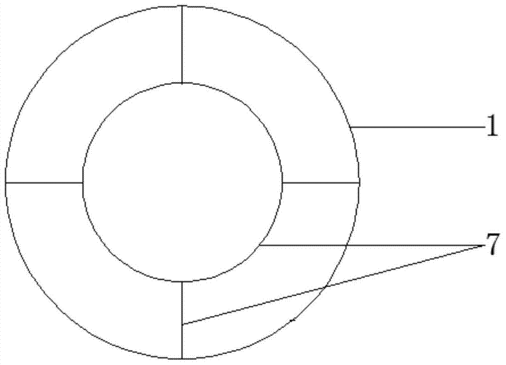
[0062] Step 1, assemble the piezoelectric unit

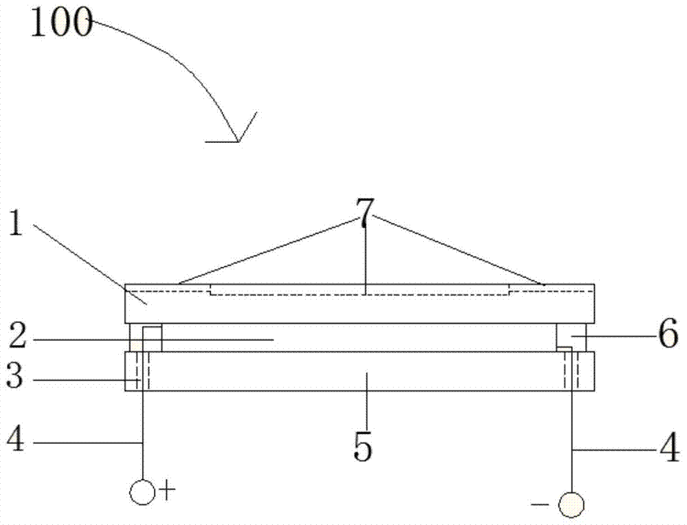
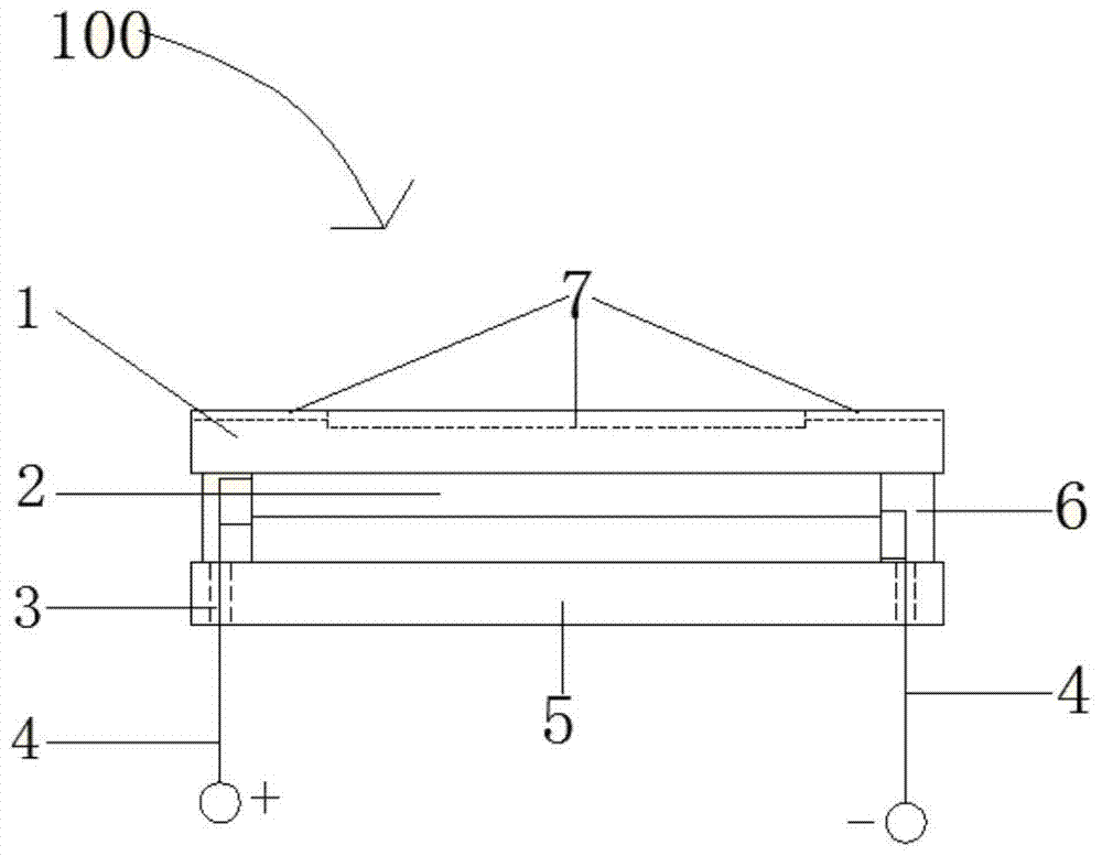
[0063] The copper plate is made of beryllium bronze circular plate, roughened on both sides to make the surface rough, and the stress absorption groove is processed by a precision lathe. The groove depth accounts for about 1 / 4 of the thickness of the copper plate, such as figure 1 As shown; the rubber pad is an ordinary circular silicon rubber pad, which is equal in size to the copper plate. It is roughened on both sides to make the surface rough, and a hole is drilled at each end of the diameter near the edge. The specific hole size is based on the total width of the wire. ; The piezoelectric element adopts a single piece of PZT piezoelectric ceramics, the diameter is slightly smaller than the copper plate and the rubber pad. Use acetone or dimethylformamide to clean the copper plate, piezoelectric element, and rubber pad and then dry them. Use epoxy resin to bond each element and package it into a piezoelectric unit, as shown ...

Embodiment 2

[0070] The steps of this embodiment are basically the same as those of Embodiment 1, except that as shown in Figure 5(b), four piezoelectric unit strips are arranged in the width direction of the road, and the corresponding piezoelectric unit in the adjacent piezoelectric unit strips The connection line between them is perpendicular to the central axis of the lane, the horizontal spacing L2 of the piezoelectric unit belt is 10cm, the longitudinal spacing of adjacent piezoelectric units in each piezoelectric unit belt is 2.5m, and the distance between the piezoelectric unit belt and the central axis of the lane is L3. L1 is 40cm.

Embodiment 3

[0072] The steps of this embodiment are basically the same as those of Embodiment 1, the difference is that: as shown in Figure 5(c), three piezoelectric unit belts are arranged in the width direction of the road, and piezoelectric unit groups are arranged on each side of the central axis of the lane. Two rows, two rows are set up next to each other; the connection between the corresponding piezoelectric units in each row of adjacent piezoelectric unit belts is perpendicular to the central axis of the lane, the transverse distance L2 of the piezoelectric unit belts is 15cm, and each piezoelectric unit belt The longitudinal distance between adjacent piezoelectric units is L3 is 2.5m, and the distance L1 between the piezoelectric unit belt and the central axis of the lane is 40cm.


PUM


Abstract

The invention discloses a generating pavement piezoelectric system and a laying method. The piezoelectric system comprises a piezoelectric unit, the piezoelectric unit comprises one or more piezoelectric elements, a copper plate, a rubber pad and an epoxy resin ring, wherein the copper plate is located above the rubber pad, and the piezoelectric elements are located between the copper plate and the rubber pad; the epoxy resin ring is arranged around the piezoelectric elements and fixedly combines the copper plate, the rubber pad and the piezoelectric elements, and the laying method comprises the steps of assembling the piezoelectric unit, preparing a mounting groove of the piezoelectric unit on the pavement and laying the piezoelectric system. The generating pavement piezoelectric system and the laying method are simple in structure, convenient to construct, good in generating performance, high in energy collecting efficiency, high in practicability and capable of achieving effective utilization of the renewable and clean energy resource and being widely applied to expressways, urban roads, special area roads and old road transformation.

Description

technical field [0001] The invention relates to the technical field of road engineering and energy collection, in particular to a piezoelectric system and a layout method for a power generation surface. Background technique [0002] With the improvement of my country's road system construction, by the end of 2014, the total mileage of my country's highways had reached 4.4639 million kilometers, of which nearly 120,000 kilometers were expressways, and the number of automobiles reached 264 million. From the open traffic to the end of life, the road surface will bear dozens or even millions of vehicle loads, and the impact and vibration of vehicle loads on the road surface will generate considerable mechanical energy. Road piezoelectric power generation provides the road impact and vibration mechanical energy into electrical energy. It is a large-scale, renewable and clean energy with huge economic and social benefits. [0003] At present, the research on the piezoelectric gen...

Claims


Application Information

Patent Timeline
Patent Type & Authority Patents(China)
IPC IPC(8): H02N2/18
CPCH02N2/183H02N2/186
Inventor 王朝辉王海梁李彦伟高志伟陈森殷卫永李岩军
Owner CHANGAN UNIV
Why Eureka
Try Eureka