
A wavelength pulse width encoding and decoding method and optical encoder

A coding and decoding method and optical coding technology, which are applied in the field of wavelength pulse width coding and decoding methods and optical encoders, can solve problems such as difficulty in realization, difficulties in practical application of technology, and complex algorithm process, and achieve low cost effects

Active Publication Date: 2017-11-28
SOUTHEAST UNIV
View PDF5 Cites 0 Cited by
  • Summary
  • Abstract
  • Description
  • Claims
  • Application Information

AI Technical Summary

Problems solved by technology

This method uses maximum likelihood estimation as the network identification algorithm, and the algorithm process is complex and difficult to implement.
[0004] The above monitoring methods have various problems in the fault monitoring of passive optical networks, especially in large user capacity networks, all kinds of problems make these technologies difficult in practical application

Method used


Image

  • A wavelength pulse width encoding and decoding method and optical encoder
  • A wavelength pulse width encoding and decoding method and optical encoder
  • A wavelength pulse width encoding and decoding method and optical encoder

Examples


Embodiment Construction

[0028] The present invention will be further described below in conjunction with embodiment and accompanying drawing.

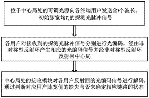
[0029] The wavelength pulse width codec method of the present invention, such as figure 1 shown, including the following steps:

[0030] Step 1. The adjustable light source located at the central office sends to each end user a wavelength of i and an initial pulse width of T s The detection light pulse signal;

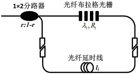
[0031] Step 2. Each user simultaneously encodes the received detection light pulse signal in the pulse width and wavelength dimensions. The encoding of the pulse width in the optical domain is realized by configuring the length of the fiber delay line in the asymmetric reflection ring, and the encoding in the wavelength domain is realized by using Bragg gratings with different central reflection wavelengths. Through the asymmetric reflection ring, the corresponding optical coded signal superimposed by multiple sub-pulses is generated and reflected ...


PUM


Abstract

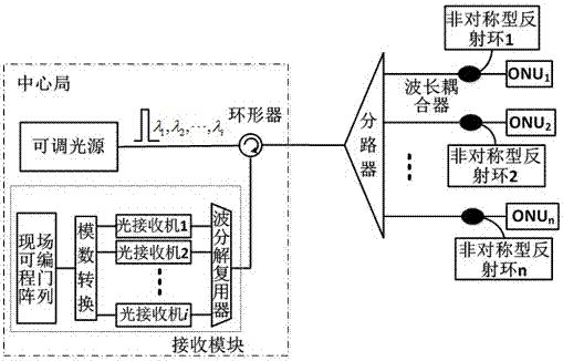
The invention discloses a wavelength pulse width encoding and decoding method and an optical encoder. The method uses wavelength and pulse width two-dimensional information to identify each user, and realizes parallel encoding in the pulse width and wavelength dimensions. The optical encoder consists of a 1×2 optical splitter, a fiber Bragg grating, and is connected through an optical fiber delay line to form an asymmetric reflection ring; parameters such as the splitting ratio of the optical splitter and the central reflection wavelength of the grating are flexible and adjustable , the maximum length of the fiber delay line is determined by the initial pulse width of the probe pulse. The method of the invention can realize arbitrary modulation of the pulse width in the optical domain, and the field programmable gate array is used at the receiving end to perform real-time pulse width measurement to complete the decoding, which can effectively release the network identification algorithm, and can ensure system performance Optical link monitoring for passive optical networks supporting large user capacity.

Description

technical field [0001] The invention belongs to the technical field of optical fiber communication, and relates to a wavelength pulse width encoding and decoding method and an optical encoder. Background technique [0002] With the large-scale advancement of "light into copper back", passive optical network is widely used in optical access network as a new and effective technology. But at the same time, with the continuous increase of the number of optical fibers in the access network, the structure becomes more and more complex, which makes it more and more important to monitor and maintain each branch link. The traditional detection and maintenance method mainly uses optical time domain reflectometer, which is suitable for point-to-point network structure, but cannot meet the monitoring requirements of point-to-multipoint access mode adopted by passive optical network system. [0003] In order to solve the problem of monitoring optical fiber links in passive optical netwo...

Claims


Application Information

Patent Timeline
Patent Type & Authority Patents(China)
IPC IPC(8): H04B10/071H04B10/077H04B10/524H04B10/2519
Inventor 孙小菡张旋陈斯陆凤军朱敏
Owner SOUTHEAST UNIV
Learn More